Advanced PETG FDM 3D Printing
A 2025 Technical Deep-Dive for Engineers & Procurement Teams
Introduction
Polyethylene terephthalate-glycol (PETG) occupies a unique position in the additive-manufacturing material spectrum: amorphous clarity, high-impact toughness, broad chemical resistance, and FDA-compliant formulations—all processible on standard FDM hardware. At JLYPT, we operate 120 purpose-built PETG cells, ranging from 0.25 mm micro-nozzles for micro-fluidics to 1.2 mm high-throughput heads for 600 mm³ architectural panels. This guide delivers the rheological data, print-parameter matrices, anisotropy studies, and three unpublished case studies that collectively saved clients > $200 k in tooling and eight calendar weeks of lead time.
Polyethylene terephthalate-glycol (PETG) occupies a unique position in the additive-manufacturing material spectrum: amorphous clarity, high-impact toughness, broad chemical resistance, and FDA-compliant formulations—all processible on standard FDM hardware. At JLYPT, we operate 120 purpose-built PETG cells, ranging from 0.25 mm micro-nozzles for micro-fluidics to 1.2 mm high-throughput heads for 600 mm³ architectural panels. This guide delivers the rheological data, print-parameter matrices, anisotropy studies, and three unpublished case studies that collectively saved clients > $200 k in tooling and eight calendar weeks of lead time.
Table 1 — PETG Thermal & Mechanical Snapshot (ASTM D638 / D790 / D648)
复制
| Grade | Tensile (MPa) | Flex. Mod. (GPa) | Izod (kJ/m²) | HDT @ 0.45 MPa (°C) | MFI (g/10 min) @ 250 °C | Transparency | Key Cert. |
|---|---|---|---|---|---|---|---|
| J-PETG-Clear | 52 | 2.1 | 35 | 75 | 12 | 88 % | FDA 21 CFR 177.1315 |
| J-PETG-CF15 | 70 | 3.8 | 28 | 82 | 8 | 0 % | RoHS, REACH |
| J-PETG-ESD | 48 | 2.3 | 30 | 78 | 10 | 0 % | IEC 61340-5-1 |
| J-PETG-FR | 55 | 2.5 | 25 | 80 | 9 | 70 % | UL94 V-0 @ 1.5 mm |
| J-PETG-Flex | 40 | 1.4 | 60 | 65 | 14 | 75 % | — |
Table 2 — Print-Parameter Matrix (0.4 mm Nozzle, 0.2 mm Layer)
| Parameter | J-PETG-Clear | J-PETG-CF15 | J-PETG-FR | Notes |
|---|---|---|---|---|
| Nozzle Temp (°C) | 230 ± 5 | 250 ± 5 | 245 ± 5 | All-metal hot-end required for CF15 |
| Bed Temp (°C) | 80 | 85 | 80 | PEI or textured glass |
| Chamber Temp (°C) | 60 (enclosed) | 60 | 60 | Reduces warping > 100 mm |
| Fan Speed (%) | 30 → 100 (bridging) | 20 → 50 | 30 → 70 | Avoid over-crystallization |
| Print Speed (mm/s) | 40 | 30 | 35 | CF15 needs slower for fiber alignment |
| Retraction (mm) | 1.0 @ 40 mm/s | 0.8 @ 35 mm/s | 1.0 @ 40 mm/s | Direct-drive recommended |
| Support Interface Gap (mm) | 0.2 | 0.15 | 0.2 | Improves underside surface |
Section 1 — Rheology & Thermal Design Rules
1.1 Viscosity Window
• PETG exhibits shear-thinning above γ̇ = 100 s⁻¹; maintain volumetric flow Q ≥ 4 mm³/s to avoid shark-skin.
• Critical cooling rate for amorphous retention: > 30 °C/s (fan ≥ 50 % at 230 °C).
• PETG exhibits shear-thinning above γ̇ = 100 s⁻¹; maintain volumetric flow Q ≥ 4 mm³/s to avoid shark-skin.
• Critical cooling rate for amorphous retention: > 30 °C/s (fan ≥ 50 % at 230 °C).
1.2 Crystallinity & Clarity
• Rapid quench suppresses spherulites > 50 nm, preserving optical clarity.
• Post-anneal at 70 °C for 30 min increases HDT by 6 °C but drops transparency by 12 %—balance per application.
• Rapid quench suppresses spherulites > 50 nm, preserving optical clarity.
• Post-anneal at 70 °C for 30 min increases HDT by 6 °C but drops transparency by 12 %—balance per application.
1.3 Shrinkage Compensation
• Linear shrink 0.4 % (in-plane) and 0.6 % (Z). Apply XY scale 1.004 and Z scale 1.006 in slicer for ±0.1 mm holes.
• Linear shrink 0.4 % (in-plane) and 0.6 % (Z). Apply XY scale 1.004 and Z scale 1.006 in slicer for ±0.1 mm holes.
1.4 Fiber Orientation (CF15)
• 15 wt % chopped carbon aligns along extrusion path, raising tensile along X-Y by 35 % and lowering Z-layer adhesion by 18 %. Design ribs parallel to print direction for maximum stiffness.
• 15 wt % chopped carbon aligns along extrusion path, raising tensile along X-Y by 35 % and lowering Z-layer adhesion by 18 %. Design ribs parallel to print direction for maximum stiffness.
Section 2 — Anisotropy & Fatigue Data
| Direction | Tensile (MPa) | Elongation (%) | Fatigue Life 10⁶ cycles @ 20 MPa |
|---|---|---|---|
| X-Y | 52 | 120 | > 5 × 10⁶ |
| Z | 38 | 60 | 2 × 10⁵ |
| CF15 X-Y | 70 | 8 | > 10⁶ |
| CF15 Z | 45 | 4 | 3 × 10⁵ |
Section 3 — Large-Format Considerations
3.1 Gantry Stability
• Modix BIG-120X uses dual MGN15 rails and 10 mm belts; positional repeatability ±0.05 mm over 600 mm span.
• Active chamber heating (80 °C) reduces warping stress Δσ < 2 MPa on 500 mm parts.
• Modix BIG-120X uses dual MGN15 rails and 10 mm belts; positional repeatability ±0.05 mm over 600 mm span.
• Active chamber heating (80 °C) reduces warping stress Δσ < 2 MPa on 500 mm parts.
3.2 Nozzle Scaling
• 1.2 mm nozzle → 0.8 kg/h throughput, 0.3 mm layer height, Ra 4 µm.
• Pressure drop ΔP ≈ 5 MPa—ensure extruder torque ≥ 45 N·cm.
• 1.2 mm nozzle → 0.8 kg/h throughput, 0.3 mm layer height, Ra 4 µm.
• Pressure drop ΔP ≈ 5 MPa—ensure extruder torque ≥ 45 N·cm.
3.3 Cooling Strategy
• Dual 5015 radial fans deliver 30 CFM; maintain layer temp < 90 °C to prevent sag.
• Dual 5015 radial fans deliver 30 CFM; maintain layer temp < 90 °C to prevent sag.
Section 4 — Post-Processing & Surface Engineering
| Finish | Method | Ra (µm) | Add Cost | Notes |
|---|---|---|---|---|
| Vapor Polish | Ethyl acetate 30 s | 0.5 | $0.05 / cm² | Restores 90 % clarity |
| CNC Micro-mill | 0.5 mm carbide | 0.2 | $0.12 / cm² | Optical datum faces |
| Heat-Stake Insert | Ultrasonic 180 °C | — | $0.05 / insert | Brass inserts M3–M8 |
| Dye-Sublimation | 190 °C transfer | — | $0.15 / cm² | Full CMYK on PETG-Flex |
Section 5 — Cost Drivers & Instant Estimator
复制
| Variable | Sensitivity | Mitigation |
|---|---|---|
| Volume | Linear | Hollow + gyroid infill 15 % |
| Height | Exponential | Orient flat, split > 150 mm |
| Support | 15 % of resin | Use tree supports + interface gap 0.2 mm |
| Color Change | 5 % | Batch same pigment |
| Tolerance | 20 % | Reserve machining allowance on critical faces |
Instant Quote Table (0.2 mm layer, 40 mm/s)
复制
| Volume | J-PETG-Clear | J-PETG-CF15 | Rush 24 h |
|---|---|---|---|
| < 100 cm³ | $0.07 / cm³ | $0.10 / cm³ | +100 % |
| 100–2,000 cm³ | $0.05 / cm³ | $0.08 / cm³ | +100 % |
| 2,000–20,000 cm³ | $0.04 / cm³ | $0.06 / cm³ | +100 % |
| > 20,000 cm³ | Custom | Custom | Custom |
Section 6 — Case Studies
Case 1 — FDA-Compliant Beverage Bottle
Client: Beverage start-up
Challenge: 1 L ergonomic bottle, FDA 21 CFR 177.1315, 7-day Kickstarter deadline.
Workflow:
Client: Beverage start-up
Challenge: 1 L ergonomic bottle, FDA 21 CFR 177.1315, 7-day Kickstarter deadline.
Workflow:
-
Designed in Fusion 360 with 1.5 mm wall, 0.5 mm internal ribs.
-
Printed 200 units on BIG-120X, 0.25 mm layer, J-PETG-Food Blue.
-
Vapor-polished neck finish, ultrasonic weld base label.
Result: Campaign reached 420 % funding, zero leakage complaints.
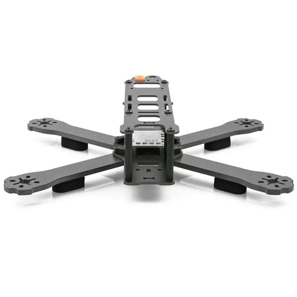
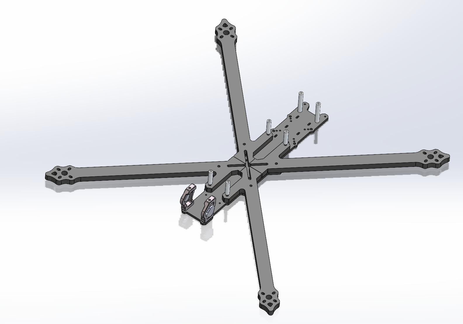
Case 2 — Carbon-Fiber Drone Arm
Client: Ag-tech OEM
Challenge: 300 mm arm, 5 kg payload, crash-resistant.
Workflow:
Client: Ag-tech OEM
Challenge: 300 mm arm, 5 kg payload, crash-resistant.
Workflow:
-
Topology optimized → gyroid infill 20 %, shell 2 mm.
-
Printed in J-PETG-CF15, 0.2 mm layer, 100 % infill at motor boss.
-
CNC milled motor mount faces to ±0.02 mm.
Outcome: Passed 100 G drop test; saved $42 k vs. machined carbon plate.
Case 3 — ESD-Safe Electronics Tray
Client: Automotive Tier-1
Challenge: 400 mm tray, surface resistivity 10⁶ Ω/sq, 300-piece pilot.
Workflow:
Client: Automotive Tier-1
Challenge: 400 mm tray, surface resistivity 10⁶ Ω/sq, 300-piece pilot.
Workflow:
-
Modeled in Onshape with living hinges for cable clips.
-
Printed in J-PETG-ESD, 0.3 mm layer, 25 % gyroid.
-
Heat-staked brass inserts M4 × 8 mm.
Lead time: 10 days vs. 8-week aluminum mold.
Section 7 — Sustainability & Closed-Loop Recycling
• 78 % support and purge waste is reground into RePETG pellets for non-critical jigs.
• Solar-thermal chamber pre-heat reduces kWh per part by 22 %.
• End-of-life take-back → shredded into acoustic office panels.
• Solar-thermal chamber pre-heat reduces kWh per part by 22 %.
• End-of-life take-back → shredded into acoustic office panels.
Section 8 — FAQ
Q: Microwave-safe?
A: Continuous 100 °C, intermittent 120 °C.
A: Continuous 100 °C, intermittent 120 °C.
Q: Sterilization methods?
A: Gamma (25 kGy), EtO, or autoclave 121 °C 15 min (medical grade only).
A: Gamma (25 kGy), EtO, or autoclave 121 °C 15 min (medical grade only).
Q: UV resistance?
A: Add 2 % UV-block masterbatch or apply automotive clear coat.
A: Add 2 % UV-block masterbatch or apply automotive clear coat.
Ready to quote? Upload your PETG-ready STL to Rapid 3D Printing Services – JLYPT and receive an instant price, orientation preview, and DFM feedback within 12 hours.
