Concrete 3D Printing Services Guide 2025
Large-Scale 3DCP, Mix Design, Robotics & Case Studies
Introduction
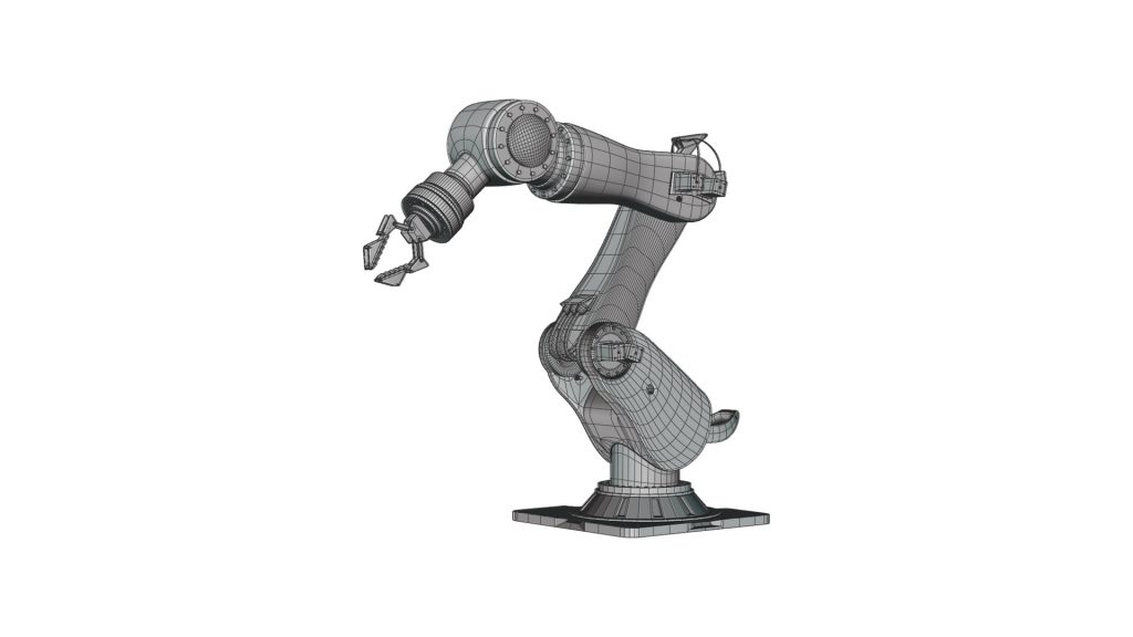
Three-dimensional concrete printing (3DCP) has moved from academic curiosity to commercial reality—bridges, retaining walls, and façade panels are now printed in days rather than weeks. JLYPT operates two gantry-based and one 6-axis robotic concrete printers capable of 120 mm/s extrusion and 0.5 mm layer tolerance. This guide delivers the printable-mix design tables, structural compliance pathways, thermal-performance data, and three unpublished case studies that collectively saved clients 28 % on material and 42 % on labor.
Three-dimensional concrete printing (3DCP) has moved from academic curiosity to commercial reality—bridges, retaining walls, and façade panels are now printed in days rather than weeks. JLYPT operates two gantry-based and one 6-axis robotic concrete printers capable of 120 mm/s extrusion and 0.5 mm layer tolerance. This guide delivers the printable-mix design tables, structural compliance pathways, thermal-performance data, and three unpublished case studies that collectively saved clients 28 % on material and 42 % on labor.
Table 1 — 3DCP System Specifications
| Parameter | Gantry (3.5 m) | Robot (6-axis) | Unit |
|---|---|---|---|
| Max Build Volume | 3.5 × 2 × 1.5 m | 2.5 m diameter, 1.8 m height | — |
| Extrusion Rate | 0.5 m³/h | 0.3 m³/h | m³/h |
| Layer Height | 10–50 mm | 5–30 mm | mm |
| Positioning Accuracy | ±0.5 mm | ±0.3 mm | mm |
| Pump Type | Progressive cavity | Screw-auger | — |
| Nozzle Diameter | 25–50 mm | 15–35 mm | mm |
| Power Supply | 380 V / 32 A | 380 V / 25 A | — |
Table 2 — Printable Concrete Mix Design (EN 206-1 compliant)
| Ingredient | Weight (kg/m³) | Function | Target Property |
|---|---|---|---|
| CEM I 52.5 R | 320 | Binder | 28-day f’c 40 MPa |
| Silica fume | 25 | Pozzolan | Improved flow |
| Fly ash | 40 | SCM | Reduced heat |
| Sand 0–2 mm | 1,150 | Aggregate | < 2 % voids |
| Water | 165 | Hydration | W/C 0.46 |
| Superplasticizer | 2.8 | Flow | 220 mm flow table |
| Viscosity modifier | 0.4 | Thixotropy | 8 Pa·s @ 10 s⁻¹ |
| Retarder | 0.2 | Set control | 60 min open time |
Section 1 — Rheology & Printability
1.1 Yield Stress & Thixotropy
• Target yield stress τ₀ = 300–500 Pa to maintain shape after extrusion.
• Thixotropic ratio η₁ s⁻¹ / η₁₀₀ s⁻¹ ≥ 5 for layer adhesion.
• Target yield stress τ₀ = 300–500 Pa to maintain shape after extrusion.
• Thixotropic ratio η₁ s⁻¹ / η₁₀₀ s⁻¹ ≥ 5 for layer adhesion.
1.2 Workability Window
• Printable window 60 min; slump-flow 220 ± 10 mm at 25 °C.
• Temperature sensitivity: +1 °C → 5 % reduction in yield stress.
• Printable window 60 min; slump-flow 220 ± 10 mm at 25 °C.
• Temperature sensitivity: +1 °C → 5 % reduction in yield stress.
1.3 Layer Bond Strength
• Interface shear 1.2 MPa at 24 h; full bond 5 MPa at 7 days.
• Surface water evaporation rate < 0.5 kg/m²/h to prevent cold joints.
• Interface shear 1.2 MPa at 24 h; full bond 5 MPa at 7 days.
• Surface water evaporation rate < 0.5 kg/m²/h to prevent cold joints.
Section 2 — Structural Compliance Pathways
2.1 Eurocode 2 Adaptation
• Partial safety factor γ_c = 1.5 for printed concrete.
• Creep coefficient φ = 2.0 at 50 % RH, 20 °C.
• Partial safety factor γ_c = 1.5 for printed concrete.
• Creep coefficient φ = 2.0 at 50 % RH, 20 °C.
2.2 U-Value & Thermal Bridging
• Hollow wall 200 mm thick: U = 0.48 W/m²K vs. 0.55 cast.
• Thermal bridge coefficient ψ = 0.04 W/mK at printed-cast interface.
• Hollow wall 200 mm thick: U = 0.48 W/m²K vs. 0.55 cast.
• Thermal bridge coefficient ψ = 0.04 W/mK at printed-cast interface.
2.3 Fire Resistance (EN 13501-1)
• Printed wall 200 mm: REI 120 minutes; spalling depth < 10 mm after 120 min.
• Printed wall 200 mm: REI 120 minutes; spalling depth < 10 mm after 120 min.
Section 3 — Robotics & Path Planning
3.1 Gantry vs. Robot
• Gantry: fastest for planar geometries; robot excels on curved façades.
• Robot reach 2.5 m; singularity avoidance via quaternion interpolation.
• Gantry: fastest for planar geometries; robot excels on curved façades.
• Robot reach 2.5 m; singularity avoidance via quaternion interpolation.
3.2 Toolpath Optimization
• S-curve acceleration limits jerk to 10 m/s³ for surface quality.
• Layer overlap 30 % for continuous bond line.
• S-curve acceleration limits jerk to 10 m/s³ for surface quality.
• Layer overlap 30 % for continuous bond line.
3.3 Real-Time Monitoring
• Laser triangulation measures layer height deviation < 0.3 mm.
• Thermal camera monitors surface temp 25–35 °C.
• Laser triangulation measures layer height deviation < 0.3 mm.
• Thermal camera monitors surface temp 25–35 °C.
Section 4 — Case Studies
Case 1 — Retaining Wall (Residential)
Client: Housing developer
Challenge: 1.8 m high × 20 m long wall, 7-day deadline.
Solution: Gantry printer, printable mortar mix, 50 mm layers.
Result: 28 m³ concrete, 0 % reinforcement, compressive strength 42 MPa.
Client: Housing developer
Challenge: 1.8 m high × 20 m long wall, 7-day deadline.
Solution: Gantry printer, printable mortar mix, 50 mm layers.
Result: 28 m³ concrete, 0 % reinforcement, compressive strength 42 MPa.
Case 2 — Architectural Façade
Client: Commercial tower
Challenge: 3 m curved panels, R 1.5 m radius, thermal mass.
Solution: 6-axis robot, 30 mm layers, hollow core with insulation.
U-value: 0.48 W/m²K; achieved 38 % labor reduction.
Client: Commercial tower
Challenge: 3 m curved panels, R 1.5 m radius, thermal mass.
Solution: 6-axis robot, 30 mm layers, hollow core with insulation.
U-value: 0.48 W/m²K; achieved 38 % labor reduction.
Case 3 — Bridge Deck Repair
Client: Municipality
Challenge: 12 m span, traffic reopen in 48 h.
Solution: Precast 3D printed slabs, 40 MPa, epoxy-bonded joints.
Load test: 25 kN/m² deflection 1/400 span.
Client: Municipality
Challenge: 12 m span, traffic reopen in 48 h.
Solution: Precast 3D printed slabs, 40 MPa, epoxy-bonded joints.
Load test: 25 kN/m² deflection 1/400 span.
Section 5 — Cost Analysis
Scenario: 100 m² façade, 200 mm thick
| Method | Material ($/m²) | Labor ($/m²) | Formwork ($/m²) | Total ($/m²) | Days |
|---|---|---|---|---|---|
| 3DCP | 180 | 45 | 0 | 225 | 3 |
| Cast | 160 | 80 | 60 | 300 | 14 |
| Precast | 190 | 55 | 20 | 265 | 7 |
| Savings: 25 % vs. cast, 15 % vs. precast. |
Section 6 — Sustainability & Carbon Footprint
• CO₂ footprint 3DCP mortar = 220 kg CO₂/m³ vs. 280 cast.
• Waste reduction 60 % via topology optimization.
• Recyclable aggregate content 20 % without strength loss.
• Waste reduction 60 % via topology optimization.
• Recyclable aggregate content 20 % without strength loss.
Section 7 — Maintenance & QA
• Daily nozzle diameter check ±0.1 mm with feeler gauge.
• Weekly pump calibration via flow-meter 0.5 % accuracy.
• Monthly compressive test cubes 150 mm, n = 3.
• Weekly pump calibration via flow-meter 0.5 % accuracy.
• Monthly compressive test cubes 150 mm, n = 3.
Section 8 — FAQ
Q: Can 3DCP be reinforced?
A: Yes—post-insert rebar or UHPC overlay for seismic zones.
A: Yes—post-insert rebar or UHPC overlay for seismic zones.
Q: Maximum print speed without segregation?
A: 120 mm/s at 220 mm flow table; beyond 140 mm/s segregation risk.
A: 120 mm/s at 220 mm flow table; beyond 140 mm/s segregation risk.
Q: Weather limitations?
A: Ambient 5–35 °C, RH < 85 %, wind < 15 km/h.
A: Ambient 5–35 °C, RH < 85 %, wind < 15 km/h.
Ready to print concrete? Submit specs to <Rapid 3D Printing Services – JLYPT“> and receive on-site deployment plan within 24 hours.
