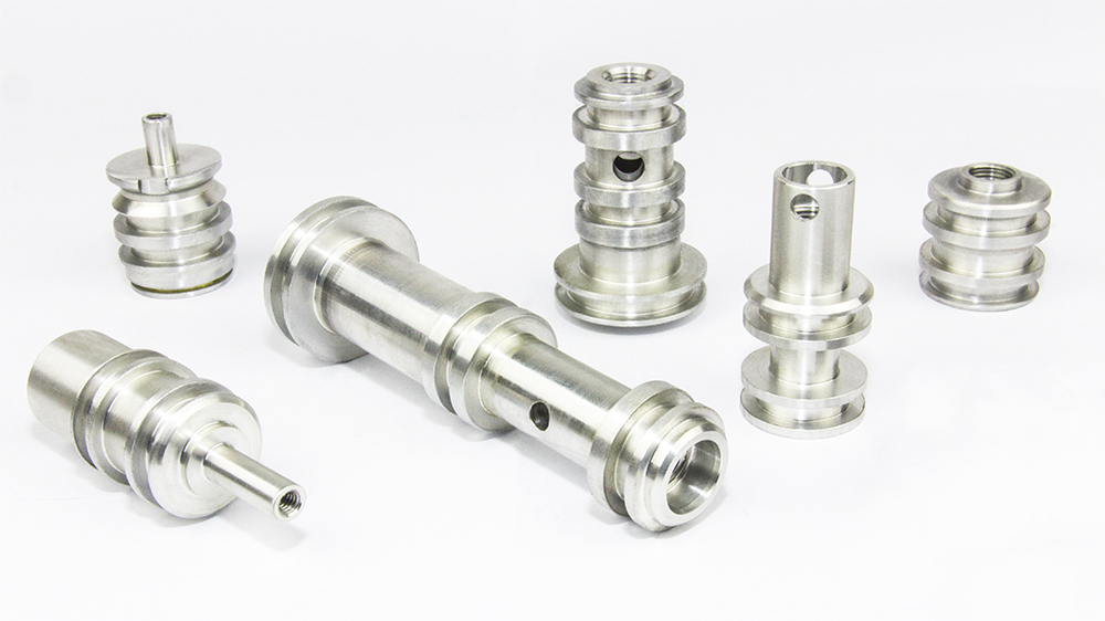
The Complete Guide to Custom Machined Components with GD&T: Precision Manufacturing for Critical Applications
Executive Summary
Custom machined components with GD&T represent the highest standard of precision manufacturing, where geometric dimensioning and tolerancing principles ensure components meet exact design specifications and functional requirements. This engineering language provides a comprehensive system for defining and communicating design intent, replacing traditional ± tolerancing with mathematically precise specifications that control form, orientation, location, and runout. For industries where precision is non-negotiable—aerospace, medical devices, automotive, and defense—GD&T offers unparalleled advantages in manufacturing efficiency, quality control, and component functionality. This guide explores the implementation of GD&T in custom machined components, detailing the standards, symbols, applications, and benefits that make this approach essential for modern precision manufacturing.
1 Introduction to GD&T in Precision Machining
Geometric Dimensioning and Tolerancing (GD&T) is a symbolic language used in engineering drawings and specifications to communicate precise requirements for manufactured components. Unlike traditional coordinate tolerancing that uses simple ± values, GD&T provides a comprehensive system that defines both the size and geometric characteristics of parts, ensuring they function as intended in their final application. The system is governed by international standards, primarily ASME Y14.5 in the United States and ISO 1101 internationally, which provide the rules and definitions for proper implementation.
The fundamental purpose of GD&T is to ensure that parts meet their functional requirements while maximizing manufacturability and inspectability. By providing clear, unambiguous specifications, GD&T eliminates guesswork in both manufacturing and quality control processes. This is particularly critical for custom machined components where precision directly impacts performance, safety, and reliability. The system establishes a common language between designers, manufacturers, and inspectors, reducing errors and misinterpretations that can lead to costly rework or component failure.
The evolution of GD&T has paralleled advancements in manufacturing technology, particularly the growth of CNC machining and computer-aided manufacturing. As machining capabilities have improved, allowing for tighter tolerances and more complex geometries, the need for a more sophisticated tolerancing system has become increasingly important. Today, GD&T is an essential component of digital manufacturing and model-based definition, where 3D CAD models containing embedded GD&T data are used throughout the product lifecycle without reference to traditional 2D drawings.
2 Fundamental GD&T Concepts and Symbols
GD&T uses a system of symbols, modifiers, and rules to comprehensively define part requirements. Understanding these fundamental elements is essential for both designing and manufacturing custom machined components.
Datums and Reference Frames: Datums are theoretically exact points, axes, or planes that establish the coordinate system from which measurements are made. The datum reference frame typically consists of three mutually perpendicular planes (primary, secondary, and tertiary datums) that provide the foundation for all geometric controls. Proper datum selection is critical, as it should reflect the part’s functional interfaces and assembly requirements.
Geometric Characteristics: GD&T defines 14 geometric characteristics symbols grouped into five categories:
-
Form controls (straightness, flatness, circularity, cylindricity)
-
Orientation controls (parallelism, perpendicularity, angularity)
-
Location controls (position, concentricity, symmetry)
-
Runout controls (circular runout, total runout)
-
Profile controls (profile of a line, profile of a surface)
Modifiers and Symbols: Various modifiers enhance the flexibility and applicability of GD&T controls:
-
Maximum Material Condition (MMC): Indicated by an M circle, this modifier allows additional tolerance as a feature deviates from its maximum material condition
-
Least Material Condition (LMC): Indicated by an L circle, this provides additional tolerance as a feature deviates from its least material condition
-
Regardless of Feature Size (RFS): The default condition where the tolerance applies regardless of the feature’s actual size
-
Projected Tolerance Zone: Indicated by a P circle, this extends the tolerance zone beyond the feature’s surface
-
Free State: Indicated by an F circle, this applies to features subject to deformation after machining
Table: GD&T Symbols and Their Applications in CNC Machining
| Symbol | Name | Control Type | Application Example | CNC Machining Consideration |
|---|---|---|---|---|
| ⌖ | Position | Location | Hole patterns, feature locations | Requires precise coordinate system alignment |
| ⏥ | Flatness | Form | Mounting surfaces, sealing faces | Dependent on tool path and machine rigidity |
| ∥ | Parallelism | Orientation | Slide surfaces, reference features | Requires machine geometry verification |
| ⟂ | Perpendicularity | Orientation | Mounting flanges, orthogonal features | Dependent on spindle squareness and setup |
| ○ | Circularity | Form | Bearings journals, rotating surfaces | Affected by tool deflection and spindle runout |
| ⌓ | Cylindricity | Form | Precision shafts, hydraulic cylinders | Requires stable cutting conditions and tool wear control |
| ↗ | Angularity | Orientation | Angled features, chamfered surfaces | Dependent on rotary axis accuracy |
| ⌒ | Profile of a Surface | Profile | Complex contours, airfoil shapes | Requires multi-axis machining capability |
| ⌓ | Circular Runout | Runout | Rotating components, bearing seats | Affected by workpiece clamping and machine accuracy |
| ⌖ | Concentricity | Location | Multiple diameters on same axis | Requires precise workpiece alignment |
3 Benefits of GD&T for Custom Machined Components
Implementing GD&T for custom machined components provides numerous advantages over traditional tolerancing methods:
Increased Functional Tolerances: GD&T typically provides 57% more tolerance zone area compared to traditional coordinate tolerancing. This is because GD&T uses cylindrical tolerance zones for features like position, which have a larger area than the square tolerance zones of ± tolerancing. This additional tolerance allows manufacturers to use more efficient processes while still meeting functional requirements.
Improved Clearance and Fit: The bonus tolerance available through MMC and LMC modifiers enables better fit and function of assembled components. For example, when a hole is produced at a size larger than its MMC, the additional position tolerance allows for easier assembly while maintaining the functional relationship between parts.
Elimination of Ambiguity: GD&T provides precise mathematical definitions of tolerance zones, eliminating the ambiguity inherent in traditional tolerancing methods. This clarity ensures that manufacturers, inspectors, and designers all interpret the requirements consistently, reducing disputes and quality issues.
Enhanced Functional Requirements: GD&T focuses on how parts function in assembly rather than just conforming to dimensional requirements. This function-based approach ensures that manufactured components will perform as intended in their final application, reducing failures and improving reliability.
Statistical Process Control Enablement: The clear definition of tolerance zones and datums in GD&T facilitates the implementation of statistical process control (SPC) in manufacturing. By understanding the exact requirements, manufacturers can better monitor and control their processes to ensure consistent quality.
Cost Reduction: Through the combination of increased tolerances, reduced ambiguity, and improved process control, GD&T typically reduces manufacturing costs by 15-30% for precision components. The reduction in scrap, rework, and inspection time contributes significantly to these savings.
4 GD&T Standards and Compliance
Implementing GD&T requires adherence to established standards and specifications:
ASME Y14.5 Standard: The American Society of Mechanical Engineers Y14.5 standard is the primary reference for GD&T in the United States and many other countries. This comprehensive standard defines the symbols, rules, and applications of geometric dimensioning and tolerancing. The current version, ASME Y14.5-2018, includes updates for modern manufacturing practices and clarifies many concepts for better implementation.
ISO 1101 Standard: The International Organization for Standardization 1101 standard governs GD&T implementation internationally. While similar to ASME Y14.5 in many respects, ISO 1101 has some important differences in symbolism and application that must be understood for global manufacturing.
Datum Reference Frame Order: Both standards emphasize the importance of proper datum selection and order in the feature control frame. The primary datum (usually listed first) establishes the initial alignment, with secondary and tertiary datums providing additional constraints to fully orient and locate the part.
Material Condition Modifiers: Understanding and properly applying MMC, LMC, and RFS modifiers is essential for compliance. These modifiers significantly affect the interpretation of tolerances and must be used consistently throughout the design.
Inspection and Verification: GD&T compliance requires specific measurement approaches and equipment capabilities. Coordinate measuring machines (CMMs), optical comparators, and specialized gages are often necessary to verify GD&T requirements properly.
Table: GD&T Standards Comparison and Applications
| Standard | Governed By | Primary Region | Key Characteristics | Common Applications |
|---|---|---|---|---|
| ASME Y14.5 | American Society of Mechanical Engineers | United States, North America | Uses material condition modifiers extensively, well-defined rules | Aerospace, defense, medical devices |
| ISO 1101 | International Organization for Standardization | Europe, International | Slightly different symbolism, emphasis on independence principle | Automotive, consumer products, industrial equipment |
| GB/T 1182 | Standardization Administration of China | China | Equivalent to ISO 1101 with minor modifications | Manufacturing for Chinese market |
| JIS B 0021 | Japanese Standards Association | Japan | Based on ISO 1101 with some unique elements | Japanese automotive and electronics |
| DIN ISO 1101 | Deutsches Institut für Normung | Germany | German implementation of ISO 1101 | Precision engineering, automotive |
5 Implementation in CNC Machining
Successfully implementing GD&T in custom machined components requires specific approaches throughout the manufacturing process:
Design for Manufacturing Review: Before machining begins, a thorough DFM review should ensure that GD&T requirements are achievable with available equipment and processes. This review should consider machine capability, tooling limitations, fixture design, and inspection methods to verify that all specified tolerances can be met consistently.
CNC Programming Considerations: GD&T requirements directly impact CNC programming strategies:
-
Datum feature simulation must be established in the machining setup
-
Tool path planning must consider form and profile requirements
-
Sequence of operations must ensure that datums are established before they are referenced
-
Cutting parameters must be optimized to achieve required surface finishes and geometric characteristics
Fixture Design and Workholding: Proper fixture design is critical for maintaining GD&T requirements, particularly for orientation and location controls. Fixtures must:
-
Simulate datum features accurately
-
Minimize distortion during machining
-
Provide adequate access for machining operations
-
Allow for proper inspection of critical features
Machining Process Control: Maintaining GD&T requirements during machining requires careful process control:
-
Machine calibration to ensure geometric accuracy
-
Tool management to prevent deflection and wear issues
-
Temperature control to minimize thermal expansion effects
-
In-process verification to detect deviations early
Quality Control and Inspection: GD&T components require sophisticated inspection approaches:
-
CMM programming that follows ASME Y14.5.1 standards
-
Proper datum establishment during measurement
-
Use of functional gages for high-volume production
-
Statistical analysis of measurement data to ensure process capability
6 Applications and Case Studies
Custom machined components with GD&T serve critical functions across industries where precision, reliability, and performance are essential:
Case Study 1: Aerospace Landing Gear Components
An aerospace manufacturer required landing gear actuators from titanium Ti-6Al-4V with stringent position tolerances and orientation controls to ensure proper function under extreme loads.
Challenge: Machine complex actuator components with position tolerances of φ0.005″ at MMC on critical bearing journals and perpendicularity of 0.001″ on mounting surfaces. Components needed to maintain structural integrity while minimizing weight for aircraft performance.
Solution: 5-axis CNC machining centers with real-time compensation maintained the required geometric tolerances throughout the machining process. Specialized fixturing simulated aircraft mounting points during machining, ensuring datums were established from functional interfaces. In-process probing verified critical features before part removal, allowing for adjustments when needed.
Results: The components achieved all GD&T requirements with Cpk values exceeding 2.0 for critical characteristics. The landing gear systems passed all functional tests and have accumulated over 500,000 flight hours without failure. The clear GD&T specifications enabled first-time-right manufacturing, reducing development time by 40% compared to previous projects.
Case Study 2: Medical Implant Components
A medical device company needed spinal implant components from PEEK material with complex geometric requirements to ensure proper fit and function in minimally invasive surgery.
Challenge: Manufacture implant components with profile tolerances of 0.002″ on mating surfaces and position tolerances of φ0.003″ on locking features. Components required biocompatible surfaces and needed to maintain dimensional stability through sterilization processes.
Solution: Multi-axis Swiss-type CNC machines with micro-tooling capabilities produced the complex geometries with the required precision. Specialized workholding minimized distortion during machining of thin-walled features. 100% automated inspection using vision systems verified all GD&T requirements without handling damage.
Results: The implant components achieved 100% compliance with all GD&T requirements, with surface finishes exceeding Ra 0.2μm on all patient-contacting surfaces. The clear GD&T callouts enabled efficient manufacturing and inspection, contributing to FDA approval on the first submission. The implants have been successfully used in over 10,000 procedures with zero device-related complications.
Case Study 3: Automotive Transmission Components
An automotive manufacturer needed transmission valve bodies from aluminum 6061 with complex port geometries and precision location requirements for proper hydraulic function.
Challenge: Machine valve bodies with position tolerances of φ0.010″ at MMC on critical fluid passages and parallelism of 0.001″ on mounting surfaces. Components needed to maintain leak-free operation under high pressure and temperature cycling.
Solution: High-speed machining centers with through-spindle coolant produced the precise geometries with excellent surface finish. Modular fixturing allowed for complete machining in a single setup, maintaining all datum relationships. Post-process inspection using CMMs verified all GD&T requirements with complete data documentation.
Results: The valve bodies achieved leak rates 50% lower than previous designs, with functional yield exceeding 99.9% in production. The GD&T implementation enabled automated inspection and statistical process control, reducing quality costs by 35% compared to traditional tolerancing methods.
7 Future Trends in GD&T and Precision Machining
The field of GD&T and precision machining continues to evolve with several emerging trends:
Model-Based Definition (MBD): The move toward fully defined 3D models containing embedded GD&T data is eliminating the need for traditional 2D drawings. MBD provides complete product definition in a single digital file, reducing errors and improving efficiency throughout the product lifecycle.
Digital Twin Technology: Virtual replicas of physical components containing GD&T data are being used for simulation, analysis, and optimization before manufacturing begins. This approach allows for virtual validation of manufacturing processes and inspection methods, reducing time to market and improving quality.
Artificial Intelligence in GD&T: AI systems are being developed to automatically generate GD&T schemes based on functional requirements and manufacturing capabilities. These systems can also optimize tolerance stacks and predict manufacturing outcomes based on historical data and simulation results.
Advanced Measurement Technologies: New measurement technologies including 3D scanning, computed tomography, and laser tracking are enabling more comprehensive verification of GD&T requirements. These technologies can capture complete surface data rather than discrete points, providing a more complete verification of geometric characteristics.
Global Standardization: Efforts are underway to harmonize GD&T standards internationally, reducing differences between ASME and ISO approaches. This standardization will facilitate global manufacturing and reduce compliance costs for international companies.
8 Conclusion: The Strategic Value of GD&T in Custom Machining
Custom machined components with GD&T represent the pinnacle of precision manufacturing, where mathematical precision in design translates to reliable performance in application. The implementation of geometric dimensioning and tolerancing provides benefits that extend throughout the product lifecycle, from design and manufacturing to inspection and final use.
The clear communication of design intent through GD&T eliminates ambiguity and reduces errors, while the increased tolerance zones allow for more efficient manufacturing processes. The functional approach of GD&T ensures that components perform as intended in their final application, reducing failures and improving reliability. Finally, the comprehensive nature of the GD&T system provides a framework for continuous improvement in manufacturing processes and quality control.
As manufacturing continues to evolve toward digital processes and smart factories, GD&T will play an increasingly important role in ensuring quality and efficiency. The integration of GD&T with model-based definition, digital twins, and artificial intelligence will further enhance its value as a cornerstone of precision manufacturing.
At JL YPT, we combine state-of-the-art CNC machining capabilities with extensive expertise in GD&T implementation to deliver custom components that meet the most demanding specifications. Our facilities include advanced machining equipment, comprehensive inspection capabilities, and engineering expertise that ensure your GD&T requirements are met consistently and efficiently.
Ready to discuss your custom machining project with GD&T requirements? Contact JL YPT today to leverage our expertise for your most critical components.


