The Engineering of Minimal Mass: Advanced CNC Machining Strategies for High-Performance Lightweight Drone Systems
Introduction: The Weight Imperative in Modern Unmanned Systems
In the domain of unmanned aerial vehicles (UAVs), the pursuit of lightweight drone construction represents far more than a simple engineering preference—it constitutes the fundamental physics governing flight endurance, agility, payload capacity, and operational range. Every gram removed from a drone’s structural mass translates directly into extended flight time, increased battery efficiency, or enhanced mission capability. At JLYPT, we specialize in the sophisticated discipline of high-performance lightweight construction through precision CNC machining, where the challenge is not merely to make components lighter, but to engineer them with maximum structural efficiency, ensuring that reduced weight never comes at the cost of diminished strength, stiffness, or reliability.
The evolution from conventional designs to truly optimized lightweight drone platforms requires a paradigm shift in manufacturing philosophy. It demands a meticulous integration of advanced materials science, computational structural analysis, and precision subtractive manufacturing techniques. This engineering approach moves beyond the simplistic removal of material to the strategic placement and shaping of matter, creating components where every cubic millimeter serves a specific structural purpose. The distinction is measurable: a topologically optimized arm machined from aerospace-grade aluminum can achieve a 40% higher stiffness-to-weight ratio than its prismatic counterpart, while a strategically skeletonized center plate can reduce mass by 30% without compromising impact resistance.
This technical exploration delves into the methodologies, materials, and machining technologies that define the forefront of lightweight drone manufacturing. We will examine how generative design algorithms work in concert with multi-axis CNC machining to produce organic, efficient structures, why materials like 7075-T6 aluminum and selective composites are chosen, and how thin-wall machining and dynamic balancing are critical for performance. For engineers and developers pushing the boundaries of what is aerially possible—from racing drones where milliseconds matter to long-endurance platforms surveying vast areas—this knowledge is the blueprint for transcending conventional design limitations. Discover how our dedicated expertise at JLYPT Custom CNC UAV Parts Manufacturer transforms the theoretical ideals of minimal mass into flight-ready, high-performance reality.
The Physics of Weight: Understanding the Performance Multiplier
Weight reduction in drones is governed by a cascade of performance equations where mass acts as the primary limiting variable. The impact is quantifiable across every aspect of flight:
-
Flight Endurance (t): Approximately proportional to the ratio of battery energy to total weight. A 10% reduction in total mass can yield an 8-12% increase in hover or cruise time, as less energy is expended to overcome gravity and inertia.
-
Power Consumption (P): Scales with weight, especially during maneuvers and climb. Lighter drones require smaller, more efficient motors and electronic speed controllers (ESCs), reducing the thermal load and electrical system complexity.
-
Agility and Control Response: The angular acceleration (α) of a drone is inversely proportional to its mass moment of inertia (I). Reduced mass, especially at the extremities (arms, motor mounts), dramatically improves roll and pitch rates, enabling faster, more precise maneuvers.
-
Payload Capacity: Any weight saved in the airframe structure is directly added to the available payload budget, whether for larger sensors, additional batteries, or delivery packages.
Therefore, the goal of lightweight drone engineering is to minimize the structural mass fraction—the percentage of the total takeoff weight consumed by the airframe itself. High-performance designs target this fraction to be below 15-20%, a figure achievable only through integrated design and precision manufacturing.
The Core Strategies for Lightweighting: A Multi-Faceted Approach
Achieving true lightness requires simultaneous optimization across four interconnected domains: Design, Material, Manufacturing Process, and System Integration.
1. Design Optimization: From Intuition to Algorithm
The era of designing by intuition is over. Modern lightweight drone structures are born from computational optimization.
-
Topology Optimization (TO): This algorithmic process starts with a defined design space (the maximum allowable volume for a part) and applies simulated operational loads (thrust, aerodynamic forces, impacts). The software iteratively removes material from areas of low stress, resulting in organic, often bone-like structures that provide the required stiffness with minimal mass. These complex geometries are uniquely suited for 5-axis CNC machining.
-
Lattice and Sandwich Structures: For larger, flat surfaces like center plates or fairings, substituting solid material with an internal microlattice or honeycomb core sandwiched between thin skins can reduce mass by over 50% while maintaining bending stiffness. These internal structures can be machined or formed and then assembled or, increasingly, created via additive manufacturing and finished with CNC machining for critical interfaces.
-
Functional Integration (Monolithic Design): The most effective way to eliminate weight is to eliminate parts. CNC machining enables monolithic construction, where what was once an assembly of an arm, a motor mount, and a bracket becomes a single, continuous piece. This removes the weight of fasteners, simplifies assembly, and increases overall stiffness by eliminating compliance at joints.
2. Material Selection: The Foundation of Performance
The choice of material sets the absolute lower bound for weight. The key metric is specific strength (strength-to-density ratio) and specific stiffness (stensity-to-density ratio).
-
Aluminum 7075-T6: The workhorse for high-performance frames. While its density (2.81 g/cm³) is similar to other aluminums, its significantly higher yield strength (~500 MPa) means you can use less of it. Walls can be designed thinner while still withstanding flight loads and crash impacts.
-
Titanium Alloys (Ti-6Al-4V): The premium choice for ultimate strength. With a density of 4.43 g/cm³ but a strength exceeding 900 MPa, titanium offers an exceptional specific strength. It is used for mission-critical, highly stressed components like main arm-to-body links or landing gear struts in heavy-lift drones, where its higher cost is justified.
-
Magnesium Alloys (e.g., AZ31B): The champion of lightweight metals at 1.77 g/cm³. Used in applications where every gram is sacred, such as FPV racing drone frames. Its use requires careful design due to lower stiffness and stringent safety protocols during CNC machining due to flammability risks.
-
Carbon Fiber Reinforced Polymer (CFRP) Composites: While typically laid up, CNC machining is crucial for creating the precise metal interface nodes (e.g., from aluminum or titanium) that connect carbon tubes to the central hub. These hybrid structures leverage the extreme directional stiffness and vibration damping of CFRP with the precision and threaded-hole integrity of machined metal.
Table 1: Material Comparison for Lightweight Drone Structures
| Material | Density (g/cm³) | Yield Strength (MPa) | Specific Strength | Stiffness (GPa) | Best Application in Lightweight Drones | Primary CNC Machining Consideration |
|---|---|---|---|---|---|---|
| 7075-T6 Aluminum | 2.81 | 450-500 | ~160-180 | 71.7 | Primary airframe, arms, motor mounts – Optimal balance of strength, machinability, and cost. | Excellent machinability. Use sharp tools to prevent material gumming. |
| 6061-T6 Aluminum | 2.70 | 275 | ~102 | 68.9 | Prototype frames, non-critical brackets, mounting plates. | Very easy to machine and weld. Lower strength requires thicker sections. |
| Ti-6Al-4V Titanium | 4.43 | 830-900 | ~187-203 | 113.8 | Critical high-stress joints, landing gear, engine mounts – Where strength/weight is paramount. | Difficult: low thermal conductivity causes heat buildup. Requires slow speeds, sharp tools, high-pressure coolant. |
| Magnesium AZ31B | 1.77 | 200-250 | ~113-141 | 45 | Ultra-lightweight racing frames, internal brackets – Final weight optimization. | Extreme Fire Hazard. Must use dry machining, specialized chip management, and strict safety protocols. |
| PEEK (Polyetheretherketone) | 1.32 | 90-100 | ~68-76 | 3.6-4.0 | Non-structural insulators, vibration-damping mounts, camera housings. | Machines like a tough plastic. Requires sharp tools and good chip evacuation to prevent melting. |
3. Precision CNC Machining: The Enabling Technology
Design and material are theoretical until rendered physically. CNC machining provides the control needed to realize lightweight designs.
-
5-Axis Machining: Essential for creating the complex, organic shapes resulting from topology optimization. It allows undercuts, curved surfaces, and machining from multiple angles in a single setup, ensuring accuracy and saving time.
-
High-Speed Machining (HSM): Using high spindle speeds and feed rates with low depth of cuts, HSM allows for the machining of thin walls (down to 0.3-0.5mm) with minimal deflection. This is crucial for creating the delicate ribs and webs of an optimized structure.
-
Trochoidal Milling: This toolpath strategy, where the end mill moves in a circular, plunging motion, maintains a constant, light load on the tool. It is ideal for machining deep pockets and the hard alloys used in lightweight frames, as it reduces heat and extends tool life, allowing for more aggressive material removal.
-
Micro-Machining: For the smallest, most intricate components—like parts for drone-based sensors or micro-drones—micro-machining with tools as small as 0.1mm in diameter can create lightweight, precise features impossible with any other method.
Advanced Engineering Considerations for Lightweight Drones
Beyond basic weight, several nuanced engineering challenges must be addressed to ensure a lightweight drone is also a high-performing and durable one.
Managing Vibration in a Lightweight Structure
A lighter structure often has a higher natural frequency, which is good. However, it can also be more susceptible to certain resonant frequencies and may transmit vibrations more readily if not properly designed.
-
Harmonic Analysis: Using FEA software to predict the natural frequencies of the frame and ensure they do not coincide with excitation frequencies from motors (e.g., at 2x, 4x RPM) or propellers.
-
Integrated Damping: Designing features like constrained layer damping pockets—small cavities in strategic locations that can be filled with a viscoelastic material to absorb vibrational energy.
-
Strategic Stiffening: Adding minimal material in the form of a gusset or rib at a calculated location can dramatically shift a problematic resonant frequency with a negligible weight penalty.
Achieving Crash Resilience with Minimal Material
A lightweight drone cannot be fragile. The goal is to design for controlled energy absorption.
-
Strategic Failure Points: Designing certain components (like sacrificial arm tips) to fail in a predictable, repairable way during a high-energy impact, protecting more critical and expensive components like the central electronics bay.
-
Energy-Absorbing Geometry: Using curved shapes and arches that can deflect and absorb impact energy rather than brittle right-angle joints that concentrate stress.
-
Material Choice: 7075-T6 aluminum, while strong, can be more brittle than 6061. In some impact-prone areas, a hybrid design or careful stress relief is necessary.
Aerodynamic Efficiency as a “Weightless” Gain
Reducing aerodynamic drag has the same effect as reducing weight: it increases flight time and efficiency.
-
Profiled Arms: CNC machining allows arms to be shaped as teardrops or airfoils rather than simple tubes, significantly reducing drag.
-
Streamlined Fairings: Creating custom, low-drag housings for batteries and electronics that integrate seamlessly with the frame’s lines.
-
Surface Finish: A smooth, machined surface (low Ra value) creates less skin friction drag than a rough composite or printed surface.
Table 2: Lightweight Drone Component Design & Machining Checklist
| Component | Primary Lightweighting Strategy | Critical CNC Machining Tolerances | Key Validation Test |
|---|---|---|---|
| Unibody Main Frame | Topology optimization; Monolithic construction; Internal lattice. | Flatness of mounting surfaces (<0.1mm); True position of motor mounts (<0.05mm). | Modal analysis (vibration); Static load test to 2x max thrust. |
| Motor Arm | Tapered design; Airfoil cross-section; Internal hollowing. | Wall thickness consistency (±0.05mm); Perpendicularity of motor mounting face (<0.03mm). | Deflection under load; Dynamic balance of motor+arm assembly. |
| Propeller (CNC-machined) | Sculpted airfoil profiles; Thin, stiff blades; Weight-matched sets. | Balance (<0.1g·cm); Pitch angle consistency (±0.2°). | Thrust test stand; High-speed photography for flutter. |
| Battery/Camera Plate | Sandwich construction (skin + lattice core); Extensive pocketing. | Parallelism between mounting surfaces; Thread integrity in thin sections. | Torsional stiffness test; Vibration transmission to camera. |
| Landing Gear | Living hinge or sprung design; Tubular vs. solid construction. | Surface finish on sliding parts; Concentricity of telescoping sections. | Drop test from 2m; Cycle test (>10,000 landings). |
Case Studies: Lightweight Principles in Action
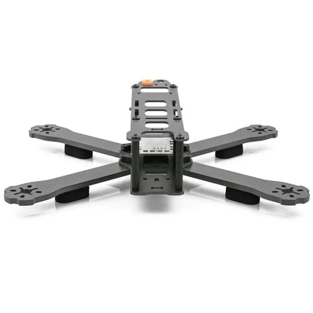
Case Study 1: The Sub-250g FPV Racing Drone (Weight-Class Champion)
-
Challenge: Design a competitive FPV racing drone frame under the 250g total weight limit (including battery and propellers) to avoid stricter regulations, while maintaining the stiffness needed for aggressive, instantaneous control at over 100 km/h.
-
JLYPT Solution:
-
Material: 3mm thick 7075-T6 sheet for the main unibody plate, with pockets machined down to 0.6mm in non-critical areas.
-
Design: A topologically optimized “spiderweb” pattern for the arms, maximizing stiffness between the motor mounts and the center while removing all non-essential material. The center section was a simple, light “sandwich” with a thin carbon fiber top plate.
-
Machining: High-speed micro-machining was used to create the intricate pocketing without distorting the thin sheet. All edges were meticulously radiused to prevent crack initiation.
-
Finish: A thin, hard ceramic coating was applied for abrasion resistance without the weight of anodizing.
-
-
Result: The final frame weighed 68 grams. It was significantly stiffer in torsion than heavier, traditional frames, giving pilots a noticeable “locked-in” feeling. The team successfully competed in the sub-250g class with a significant performance advantage.
Case Study 2: Long-Endurance Mapping Drone with Hybrid Construction
-
Challenge: Create a durable, fixed-wing mapping drone with a 2-meter wingspan capable of 4-hour flight times. The structure needed to be light for endurance but robust enough for autonomous launches and landings in field conditions.
-
JLYPT Solution:
-
Hybrid Design: The primary wing spar was a CNC-machined 7075-T6 I-beam with integral mounting points for ribs and payload. The fuselage was a carbon fiber monocoque for its excellent damping, with CNC-machined aluminum bulkheads bonded in at critical load points (wing attach, motor mount, landing gear).
-
Lightweighting: The aluminum spar was designed using sizing optimization, varying its web and flange thickness along its length based on the bending moment diagram, saving over 100g compared to a uniform spar.
-
Integration: All mating surfaces between carbon and metal were machined to a precise sealant groove pattern for a strong, reliable adhesive bond.
-
-
Result: The hybrid airframe achieved a dry weight 25% lower than an all-aluminum equivalent. The 4-hour endurance target was met and exceeded, and the drone survived hundreds of rough field operations without structural issues.
Case Study 3: Heavy-Lift Drone with Optimized Payload Efficiency
-
Challenge: For a drone designed to carry 10kg of sensor payload, optimize the airframe to maximize the payload-to-takeoff-weight ratio. The frame needed to be incredibly stiff to prevent oscillation under the slung load.
-
JLYPT Solution:
-
Material & Process: The entire central “spider” hub connecting eight arms was 5-axis machined from a solid block of Ti-6Al-4V. Titanium was chosen for its unmatched specific strength, allowing for a very stiff, compact hub.
-
Design: The hub was a masterpiece of topology and lattice optimization. It resembled a metal sponge, with a dense, strong core around bearing housings transitioning to a light, open lattice at the arm interfaces. Internal channels were machined for power distribution wiring.
-
Arm Design: The arms were carbon fiber tubes for lightweight stiffness, attached to the titanium hub via CNC-machined aluminum conical couplings for perfect alignment and load transfer.
-
-
Result: The titanium hub, despite its high material density, was lighter and over 300% stiffer than a previous welded aluminum assembly. This dramatically improved flight stability with the heavy payload and increased the operational payload capacity by nearly 15%.
Conclusion: The Synergy of Design, Material, and Precision
Building a truly high-performance lightweight drone is an exercise in systems engineering. It requires the synergistic application of intelligent design (guided by algorithms), advanced materials (chosen for specific properties), and precision manufacturing (to accurately realize the design in the chosen material). CNC machining is the indispensable bridge that connects digital optimization to physical performance.
At JLYPT, we view each project through this integrated lens. We don’t just receive a file and cut metal; we collaborate to understand the performance goals, advise on material and design trade-offs, and apply the most appropriate advanced machining techniques to produce a component that is not just light, but is efficiently light—engineered to carry its specific loads with elegant minimalism.
Is your next project pushing the limits of weight and performance? Partner with a manufacturer that understands the engineering behind the grams. Contact our team to discuss how we can help you design and manufacture the lightweight, high-performance foundation your next drone innovation requires. Explore our capabilities at JLYPT Custom CNC UAV Parts Manufacturer.