
Custom CNC UAV Parts Manufacturer: A Practical CNC Machining Playbook for Flight-Critical Drone Components (JLYPT)
UAV programs fail in predictable places: fasteners loosen, arms resonate, motor mounts ovalize, bearing seats wander out of round, and “perfectly good” prototypes become inconsistent production hardware. The difference between a drone that merely flies and a drone that flies precisely—repeatably, quietly, and under load—often comes down to machining discipline: datums that make sense, surfaces finished for real interfaces, and inspection that matches the physics of vibration and thrust.
This guide is written for engineers, product teams, and sourcing managers evaluating a Custom CNC UAV Parts Manufacturer for prototype and production. It is intentionally manufacturing-centric: materials, CNC process planning, tolerance strategy, surface finishing, and quality control—plus three detailed case studies based on real-world UAV part requirements.
If you’re looking for a direct capability overview and quotation pathway, this is the internal link you’ll want to keep handy:
https://www.jlypt.com/custom-cnc-uav-parts-manufacturer/
Table of Contents
- What “Custom CNC UAV Parts Manufacturer” Means in Practice
- Why CNC Machining Still Dominates Critical UAV Hardware
- UAV Component Map: What Gets CNC Machined (and Why)
- Materials for UAV CNC Parts: Strength, Weight, Heat, Corrosion
- CNC Processes for UAV Parts: 3-Axis, 5-Axis, Turning, Mill-Turn
- Tolerances & GD&T for UAV Assemblies Under Vibration
- Surface Finish & Edge Control: Where Reliability Is Won
- Surface Treatments: Anodize, Chem Film, Nickel, Passivation, Coatings
- Inspection & Quality Planning: From First Article to Production Control
- DFM for UAV CNC Parts: Cost, Lead Time, and Assembly Yield
- Three UAV CNC Case Studies (Realistic Build Scenarios)
- RFQ Checklist for a Custom CNC UAV Parts Manufacturer
- References (External DoFollow Links)
- FAQ
1) What “Custom CNC UAV Parts Manufacturer” Means in Practice
A Custom CNC UAV Parts Manufacturer is not just a machine shop that can cut aluminum. For UAVs, “custom” typically implies at least one of the following:
- Flight-critical interfaces: motor alignment, bearing seats, gearbox housings, vibration isolator mounts, gimbal references
- Weight-driven geometry: thin ribs, pockets, lattice-like frames, topology-inspired shapes that are difficult to fixture
- Small-batch iteration: frequent ECO updates, rapid prototype loops, and revision control
- Mixed materials and finishes: 6061 vs 7075 vs titanium, hard anodize vs chem film, stainless inserts, helicoils, thread locking strategies
- Inspection complexity: true position, concentricity, coaxial bores, flatness, parallelism, and controlled runout for rotating groups
In other words, a Custom CNC UAV Parts Manufacturer helps you manage the manufacturing reality behind performance claims: stiffness-to-weight, thrust-line alignment, vibration signature, and serviceability.
What JLYPT does in that role
As JLYPT CNC machining, our work typically centers on:
- CNC milling of frames, arms, brackets, payload mounts, avionics housings
- CNC turning / mill-turn for hubs, spacers, shafts, collars, bearing seats
- Post-processing planning (anodize allowance, masking, insert strategy)
- Inspection planning (CMM strategy aligned to functional datums)
- Prototype-to-production support with repeatable fixturing
2) Why CNC Machining Still Dominates Critical UAV Hardware
UAV platforms use many manufacturing methods—composites, injection molding, sheet metal, additive manufacturing—but CNC remains dominant in areas where you must control:
- Geometry at interfaces (motor centerlines, bolt circles, dowel features)
- Concentricity and runout for rotating parts
- Bearing seat accuracy for efficiency and durability
- Heat paths for ESC and motor thermal management
- Dimensional repeatability across production lots
Table 1 — UAV Manufacturing Methods vs Typical Use Cases
| Method | Best For | Key Advantages | Typical Limitations | Where CNC Still Wins |
|---|---|---|---|---|
| CNC machining | frames, mounts, housings, hubs | high accuracy, strong materials, repeatable | higher unit cost than molding at scale | tight fits, datums, complex metal interfaces |
| Carbon fiber layup | arms, plates | high stiffness/weight | drilling/edge quality; inserts; anisotropy | metal inserts, clamp blocks, machined interfaces |
| Injection molding | shells, covers | low cost at volume | tooling time/cost; tolerance limits | precision mounts and load paths |
| Sheet metal | brackets | quick and inexpensive | limited stiffness for certain forms | 3D stiffness, bearing seats |
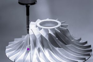
| Additive manufacturing | ducts, prototypes | fast complex shapes | anisotropy, surface finish, tolerance | flight-critical fits, post-machining needed |
A Custom CNC UAV Parts Manufacturer is often the “backbone supplier” that makes the load-bearing, alignment-critical, and service-critical parts that tie the whole platform together.
3) UAV Component Map: What Gets CNC Machined (and Why)
CNC-machined UAV components typically fall into six functional groups:
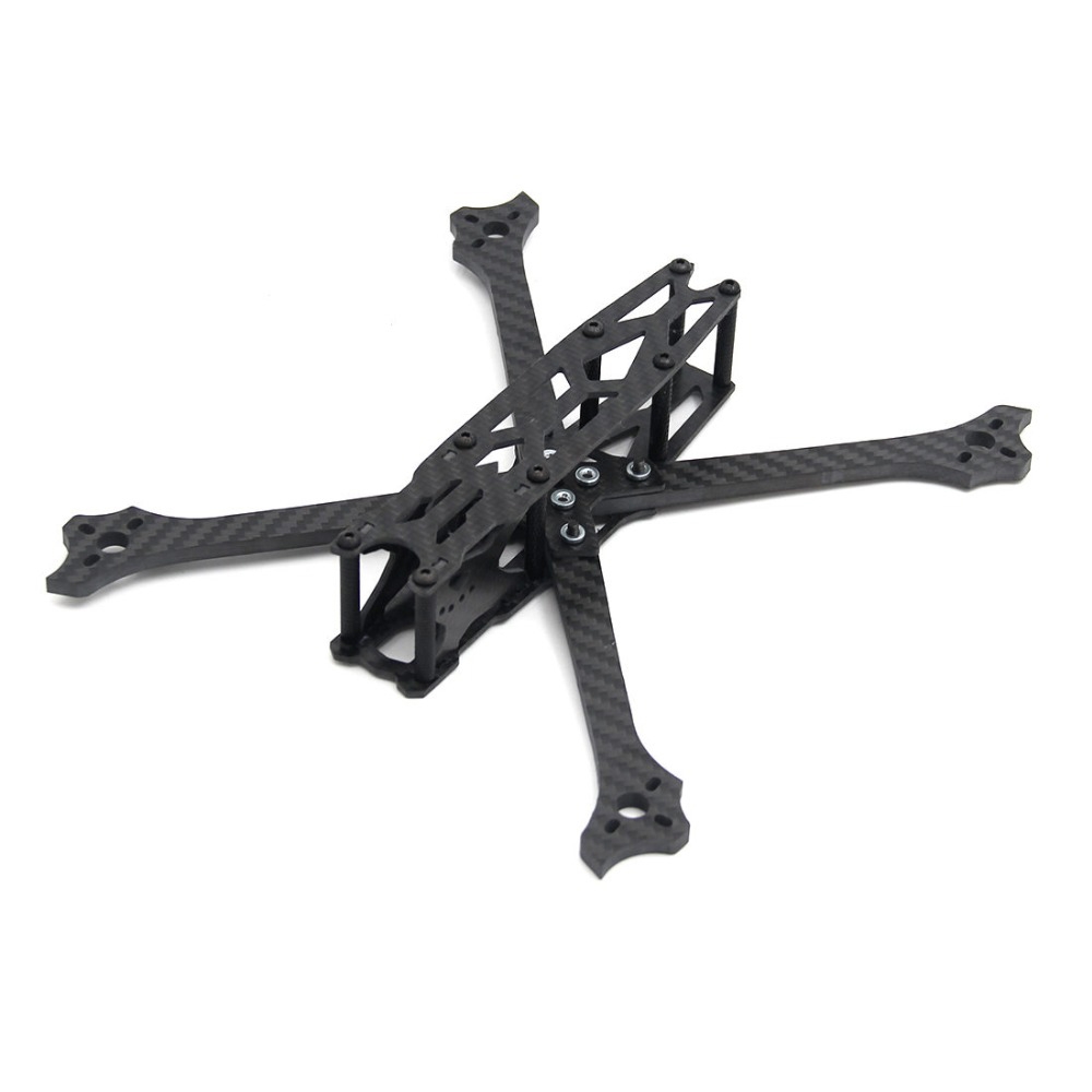
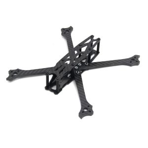
- Airframe structure (frames, arms, plates, clamp blocks)
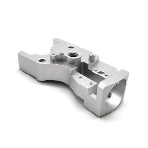
- Propulsion interfaces (motor mounts, hub adapters, prop guards, gearbox housings)
- Payload integration (gimbal brackets, camera cages, LiDAR mounts, antenna mounts)
- Avionics and power (enclosures, heatsinks, ESC trays, battery cages)
- Landing and handling (landing gear, quick-release latches, transport brackets)
- Test and calibration (jigs, fixtures, alignment gauges)
Table 2 — Common CNC-Machined UAV Parts and the Machining “Gotchas”
| Part | Typical Function | Common Material | Machining Risk | Functional Feature to Control |
|---|---|---|---|---|
| Motor mount plate | thrust alignment | 6061/7075 | distortion, thread pullout | flatness, bolt circle position |
| Arm clamp block | arm retention | 7075 | stress concentration | fillet radii, clamp symmetry |
| Hub adapter | prop interface | 7075 / 17-4PH | runout, imbalance | concentricity, face runout |
| Payload bracket | sensor alignment | 6061 | vibration coupling | stiffness + hole true position |
| ESC heatsink tray | thermal path | 6061 | warped surfaces | flatness, contact area |
| Gearbox housing | torque transmission | 7075 / 17-4PH | bearing misalignment | bore coaxiality, surface finish |
| Landing leg knuckle | impact load | 7075 / Ti | fatigue at corners | smooth transitions, finish |
| Avionics enclosure | protection/EMI | 6061 | sealing groove errors | O-ring gland geometry |
A capable Custom CNC UAV Parts Manufacturer will ask you which features are “cosmetic” and which are “flight-critical.” The machining plan and inspection plan should follow that same hierarchy.
4) Materials for UAV CNC Parts: Strength, Weight, Heat, Corrosion
Material choice is not only about strength-to-weight; it’s also about:
- machinability and dimensional stability
- compatibility with coatings
- galvanic corrosion behavior (especially with carbon fiber)
- fatigue performance under vibration
Table 3 — Material Selection Guide for UAV CNC Machining
| Material | Typical UAV Use | Pros | Cons | Notes for a Custom CNC UAV Parts Manufacturer |
|---|---|---|---|---|
| 6061-T6 Aluminum | frames, trays, brackets | excellent machinability, good corrosion | lower strength than 7075 | great for prototypes and general structures |
| 7075-T6 Aluminum | arms, clamps, high-load mounts | very high strength-to-weight | more expensive; corrosion sensitivity | often paired with hard anodize; manage stress risers |
| 2024 Aluminum | specialized aerospace parts | fatigue strength | corrosion; less common in consumer UAV | requires careful corrosion protection |
| 17-4PH Stainless | hubs, shafts, hardware | strength + corrosion | heat treat distortion possible | consider post-HT finishing for runout control |
| 304/316 Stainless | wet environments | corrosion resistance | lower strength; gummy machining | good for fasteners, brackets in washdown use |
| 4140/4340 Steel | drive components | high fatigue strength | corrosion; heavier | nitriding / oxide often used |
| Titanium (Ti-6Al-4V) | weight-critical mounts | high strength-to-weight; corrosion | slow machining; cost | useful for landing joints, compact mounts |
| Engineering plastics (POM/PEEK) | isolators, covers | low weight; damping | creep; lower stiffness | good for non-structural pieces |
Carbon fiber + aluminum: plan for galvanic corrosion
If your UAV uses carbon fiber arms/plates and machined aluminum clamp blocks, the interface should be treated as an engineering system:
- isolate with coatings, sealants, or insulating layers
- avoid bare metal contact when possible
- select fasteners and inserts carefully
A serious Custom CNC UAV Parts Manufacturer can support these choices with finishing options and assembly guidance, not just cutting chips.
5) CNC Processes for UAV Parts: 3-Axis, 5-Axis, Turning, Mill-Turn
UAV components tend to look simple until you try to hold them without distortion—or until you need multiple faces to be truly referenced to a single datum axis.
5.1 CNC Milling for UAV Frames and Brackets
- 3-axis milling covers many plates, trays, and brackets efficiently.
- 3+2 indexing (positional 5-axis) reduces setups for multi-face parts.
- full 5-axis shines for complex frames, contoured brackets, and parts that must maintain true position across faces.
Table 4 — When to Use 3-Axis vs 5-Axis in UAV CNC Machining
| Geometry | Recommended Process | Why | Typical Benefit |
|---|---|---|---|
| flat plates with pockets | 3-axis | simple fixturing | lowest cost per part |
| multi-face bracket with angled planes | 3+2 | fewer setups | better datum transfer |
| contoured payload cage | 5-axis | tool access without refixturing | improved surface finish + position |
| lightweight frame with deep pockets | 5-axis | optimal approach angles | less chatter, less distortion |
5.2 CNC Turning for Hubs, Spacers, and Rotating Interfaces
Propulsion-related components commonly require turning operations:
- hub adapters
- motor shaft collars
- bearing spacers
- pulley or gear interfaces
- precision standoffs
For rotating interfaces, the machining plan must protect:
- concentricity
- face runout
- surface finish on seats
- balanced material removal to reduce distortion
Table 5 — Turning Parameters That Matter for UAV Rotating Components
| Feature | Why It Matters in UAVs | Typical Control Method |
|---|---|---|
| concentricity of bore to OD | reduces vibration and imbalance | single-setup turning; soft jaws |
| face runout | reduces prop wobble | finish face and pilot together |
| surface finish on seats | prevents fretting and looseness | controlled feeds/speeds; optional polish |
| thread quality | prevents loosening | proper thread class; gauge check |
5.3 Mill-Turn for Compact, Coaxial, Multi-Feature Parts
Mill-turn is valuable for parts that require both turned concentric features and milled bolt patterns/keyways without losing alignment.
A Custom CNC UAV Parts Manufacturer with mill-turn capability can often reduce:
- setup count
- datum transfer error
- lead time for complex hubs and couplers
6) Tolerances & GD&T for UAV Assemblies Under Vibration
UAV tolerancing is not only about “fit.” It’s about maintaining alignment through:
- vibration
- temperature swings
- cyclic thrust loads
- repeated maintenance (disassembly/reassembly)
6.1 What to control tightly (and what not to)
Many UAV designs become expensive because everything is held to ±0.01 mm without a functional reason. The better approach is to identify:
- primary datums that define thrust-line and payload reference
- critical interfaces (bearing seats, motor pilots, dowel locations)
- non-critical geometry where looser tolerances are safe
Table 6 — Typical UAV Critical Features and Practical Tolerance Ranges
| Feature | Typical Importance | Practical Range (Example) | Why |
|---|---|---|---|
| motor pilot diameter | high | ±0.01–0.02 mm | controls motor centering and thrust alignment |
| motor mount flatness | high | 0.02–0.05 mm | avoids tilt and induced vibration |
| bolt circle true position | high | 0.05–0.10 mm | prevents assembly stress and misalignment |
| bearing seat diameter | high | depends on fit strategy | prevents creep, controls preload |
| frame pocket wall thickness | medium | ±0.10–0.20 mm | weight control, not alignment-critical |
| cover cosmetic surfaces | low | ±0.20–0.50 mm | cost reduction area |
6.2 GD&T that improves real-world UAV performance
For a Custom CNC UAV Parts Manufacturer, the most valuable GD&T callouts tend to be:
- true position of motor bolt circles relative to a pilot
- perpendicularity of mounting face to pilot axis
- flatness of heat spreader interfaces
- runout on hub faces
Table 7 — GD&T Callouts Commonly Used in UAV CNC Parts
| Part | GD&T Callout | Functional Benefit |
|---|---|---|
| motor mount | perpendicularity of face to pilot | reduces motor tilt and vibration |
| hub adapter | circular runout to bore axis | smoother rotation, less imbalance |
| gimbal bracket | true position of sensor holes | repeatable camera alignment |
| ESC tray | flatness | improved thermal contact |
If you want fewer “mystery vibrations” during test flights, align your drawing’s datums with the system’s real axes: motor thrust axis, prop axis, gimbal axis, and payload line-of-sight.
7) Surface Finish & Edge Control: Where Reliability Is Won
A UAV part can be dimensionally correct and still problematic if it has:
- burrs that cut wires
- sharp edges that initiate fatigue cracks
- rough bearing seats that fret
- inconsistent contact patches on thermal interfaces
Table 8 — Surface Finish Targets (Typical UAV CNC Guidelines)
| Interface | Suggested Ra | Why It Matters |
|---|---|---|
| motor mount face | 1.6–3.2 µm | stable seating, good torque retention |
| bearing seat | 0.4–0.8 µm | reduces fretting, stabilizes fit |
| sealing land | 0.8–1.6 µm | improves seal life |
| cable routing channels | ≤1.6 µm | reduces abrasion |
| cosmetic exterior | 1.6–3.2 µm | consistent anodize appearance |
Edge breaking and deburring
A Custom CNC UAV Parts Manufacturer should treat deburring as a controlled process, not a “handwave”:
- specify edge break (e.g., 0.2–0.5 mm)
- pay attention to internal cable cutouts
- remove burrs around tapped holes to avoid false torque readings
- maintain clean threads after finishing
8) Surface Treatments: Anodize, Chem Film, Nickel, Passivation, Coatings
Finishing is not only aesthetics. For UAVs, surface treatments influence:
- wear
- corrosion resistance
- galvanic behavior
- assembly torque stability
- dimensional outcomes
Table 9 — Common UAV Finishes and When to Use Them
| Finish | Works Best For | Advantages | Cautions |
|---|---|---|---|
| Type II anodize | general aluminum parts | corrosion resistance, color | limited wear resistance |
| Type III hard anodize | clamp blocks, wear points | high wear resistance | dimensional growth; masking needed |
| chromate conversion (chem film) | aerospace-style assemblies | good conductivity + corrosion | less abrasion resistance |
| electroless nickel | complex shapes, wear + corrosion | uniform thickness | build-up affects fits |
| passivation | stainless parts | corrosion improvement | does not fix poor material choice |
| bead blast + anodize | cosmetic frames | uniform look | may change surface contact behavior |
A reliable Custom CNC UAV Parts Manufacturer will plan finish allowance early, especially for:
- pilots
- bearing seats
- threaded features where coating can change torque behavior
9) Inspection & Quality Planning: From First Article to Production Control
You cannot “inspect quality into a part,” but you can absolutely design inspection so that problems are found early—before they become field failures.
9.1 Inspection tools typically used for UAV CNC parts
- CMM for true position, flatness, perpendicularity, coaxiality
- bore gauges for bearing seats and pilots
- surface roughness tester for seats and sealing lands
- thread gauges (Go/No-Go) for tapped holes
- coating thickness gauge where applicable
Table 10 — Example Control Plan for a UAV Motor Mount (CNC)
| Characteristic | Method | Frequency | Typical Reason |
|---|---|---|---|
| pilot diameter | bore gauge / CMM | 100% (critical) | motor centering |
| mount face flatness | CMM / surface plate | sampling or 100% | motor seating |
| bolt circle true position | CMM | sampling | avoids stress and misalignment |
| thread quality | Go/No-Go | 100% | torque retention |
| anodize thickness (if used) | thickness gauge | per lot | fit consistency |
9.2 First Article Inspection (FAI) philosophy for UAV parts
For a Custom CNC UAV Parts Manufacturer, FAI should confirm:
- datum scheme works in real fixturing
- tolerances are achievable without heroic rework
- finishing does not break fits
- assemblies go together without “persuasion”
If your UAV program is scaling, define critical characteristics and require consistent reporting so quality doesn’t silently drift.
10) DFM for UAV CNC Parts: Cost, Lead Time, and Assembly Yield
DFM in UAV machining is about spending precision where it returns performance. Common cost drivers include:
- excessive tight tolerances on non-critical surfaces
- too many setups due to poor datum design
- deep pockets that require long tools (chatter risk)
- thin walls without fixturing strategy
- complex finishing without masking notes
Table 11 — DFM Changes That Typically Reduce Cost (Without Hurting Performance)
| DFM Move | Why It Helps | Typical Result |
|---|---|---|
| loosen non-critical tolerances | reduces cycle time + inspection | lower price, faster lead time |
| add fillets/radii | improves toolpath and fatigue | fewer cracks, better durability |
| unify fastener sizes | simplifies assembly and spares | faster service and lower BOM |
| add locating features (dowels/bosses) | improves repeatability | less assembly variation |
| avoid ultra-deep narrow pockets | reduces chatter and tool wear | higher yield, better finish |
A strong Custom CNC UAV Parts Manufacturer will provide manufacturing feedback early—before parts are released and rework becomes normal.
11) Three UAV CNC Case Studies (Realistic Build Scenarios)
Below are three representative scenarios that show how CNC process decisions map directly to flight behavior, assembly yield, and field reliability. Details are generalized to protect customer confidentiality while keeping the engineering lessons concrete.
Case Study 1 — 7075 UAV Arm Clamp Blocks (Hard Anodize, Vibration-Resistant Assembly)
Application: multi-rotor arms clamped to a central frame, repeated service cycles, high vibration.
Primary requirements
- clamp faces parallel and stable under torque
- no arm slip during aggressive maneuvers
- corrosion protection compatible with mixed materials
Manufacturing plan (Custom CNC UAV Parts Manufacturer workflow)
- Material: 7075-T6 for strength-to-weight
- CNC: 3+2 or 5-axis to complete clamp faces and locating features with minimal refixturing
- Machining strategy: rough pockets early, finish clamp faces late to minimize distortion
- Critical controls: clamp face parallelism; hole true position; thread engagement
- Finish: Type III hard anodize with masking on critical locating surfaces where needed
- Inspection: CMM verification of true position and clamp geometry; thread gauge 100%
Result (typical outcomes)
- improved clamp consistency across lots
- reduced arm micro-slip complaints
- better cosmetic consistency after anodize due to controlled surface prep
Key takeaway: for structural UAV clamps, stable contact geometry and controlled finishing matter more than chasing extreme size tolerances everywhere.
Case Study 2 — CNC-Turned Hub Adapter (Concentricity-Controlled, Lower Vibration)
Application: prop hub adapter that must run true to reduce vibration and improve IMU signal quality.
Primary requirements
- low face runout at prop seating surface
- concentric pilot and bolt circle alignment
- repeatable assembly torque without thread damage
Manufacturing plan
- Material: 7075-T6 (or 17-4PH depending on environment and torque needs)
- Process: single-setup turning for bore/OD/face; secondary milling for bolt pattern in a datum-preserving fixture (or mill-turn)
- Critical controls: circular runout to bore axis; face runout; bolt circle true position
- Edge control: deburr around holes to avoid torque loss and assembly grit
- Inspection: dial indicator runout check + CMM for bolt pattern position
Result
- reduced vibration-related tuning time
- improved consistency between replacement parts
- fewer “mystery resonance” events at certain RPM bands
Key takeaway: for rotating parts, a Custom CNC UAV Parts Manufacturer must prioritize coaxiality and runout control, not just “it fits.”
Case Study 3 — Payload / Gimbal Mount Bracket (5-Axis, Alignment-Focused)
Application: camera/LiDAR mount where alignment repeatability affects mapping accuracy and post-processing.
Primary requirements
- consistent sensor datum plane
- minimal flex under acceleration and wind
- tidy cable management and strain relief
Manufacturing plan
- Material: 6061-T6 for machinability; 7075 if stiffness demands increase
- CNC: 5-axis to maintain true position across multiple angled faces and minimize setup stack
- Features: machined datum bosses, controlled flatness on sensor interface, cable slots with smooth radii
- Finish: anodize (Type II) for corrosion + appearance; optional bead blast for uniform texture
- Inspection: CMM verification of datum plane flatness and hole true position; burr inspection on cable paths
Result
- faster payload alignment during assembly
- fewer cable wear issues
- improved repeatability for field-swapped sensors
Key takeaway: payload parts succeed when the drawing defines real datums and the machining process preserves them through minimal refixturing.
12) RFQ Checklist for a Custom CNC UAV Parts Manufacturer
If you want accurate pricing and fewer clarification loops, include:
Drawing and specification package
- 2D drawings with GD&T where functional
- 3D CAD (STEP preferred)
- material spec (e.g., 6061-T6, 7075-T6)
- finish spec (Type II/III anodize, chem film, etc.)
- any masking requirements
- critical characteristics list (what must be 100% inspected)
Assembly and functional notes
- mating parts overview (motor model, bearing series, inserts)
- torque specs if threads are load-bearing
- environment notes (salt fog, rain, temperature range)
- service cycle expectation (how often disassembled)
Table 12 — What to Tell Your Supplier (So You Get Better Parts Faster)
| Information | Why It Matters | Typical Benefit |
|---|---|---|
| which features are datums | drives fixturing and inspection | better repeatability |
| target weight constraints | influences pocket strategy | lower mass without distortion |
| vibration sensitivity | prioritizes runout and symmetry | smoother flight |
| finish + masking | prevents fit failures post-coating | fewer reworks |
| expected production volume | informs tooling/fixtures | stable quality at scale |
When you send this level of detail to a Custom CNC UAV Parts Manufacturer, you get more than a quote—you get a process that’s designed to hit performance.
13) References (External DoFollow Links)
The following are helpful, general reference points for standards and measurement practices relevant to UAV manufacturing and CNC machining:
- ISO standards (GD&T and general manufacturing standards overview): https://www.iso.org/standards.html
- ASTM standards (materials and testing references): https://www.astm.org/standards
- NIST (measurement fundamentals and engineering resources): https://www.nist.gov/
- FAA drone information hub (regulatory awareness for UAV programs): https://www.faa.gov/uas
(These links are for background and terminology alignment; your drawing package should define the exact tolerances, finishes, and acceptance criteria for your parts.)
14) Why JLYPT as Your Custom CNC UAV Parts Manufacturer
If you are evaluating a Custom CNC UAV Parts Manufacturer for flight hardware, the practical question is not “Can you machine aluminum?” It’s:
- Can you hold the datums that control thrust alignment and payload reference?
- Can you manage distortion in lightweight geometries?
- Can you plan finishing so post-coating fits still assemble correctly?
- Can you inspect critical features in a way that matches how the part functions?
JLYPT focuses on CNC process planning that supports repeatability—prototype speed without sacrificing production discipline.
Internal link (capability page):
https://www.jlypt.com/custom-cnc-uav-parts-manufacturer/
Optional internal navigation (main site entry):
https://www.jlypt.com/
FAQ (Manufacturing-Focused)
How do I choose between 6061 and 7075 for UAV CNC parts?
6061 is cost-effective with excellent machinability and corrosion resistance; 7075 provides significantly higher strength and stiffness for arms, clamps, and high-load mounts. A Custom CNC UAV Parts Manufacturer will often recommend 6061 for early prototypes and 7075 for flight-like structural iterations—depending on load paths and fatigue risk.
Should I use hard anodize on UAV structural parts?
Hard anodize is excellent for wear surfaces and clamp blocks, but it changes dimensions. For parts with tight pilots or bearing seats, the finishing plan must include allowance and masking notes. This is a common “make-or-break” detail when selecting a Custom CNC UAV Parts Manufacturer.
What inspection matters most for reducing UAV vibration?
For rotating interfaces: concentricity and runout (plus stable seating faces). For structures: hole true position and consistent contact surfaces that prevent micro-slip. A good supplier will inspect the features that actually drive vibration rather than measuring only easy dimensions.


