
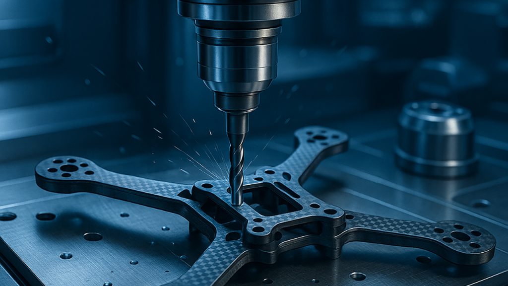
CNC Prototype Machining for Drones: A Practical, Shop-Floor Guide to Faster Iteration and Cleaner Flight Tests
Drone development punishes vague manufacturing. You can “get a part made” and still lose weeks chasing vibration, misalignment, thermal issues, or assembly headaches that were quietly baked into the prototype. That’s why CNC prototype machining for drones isn’t just a quick way to produce hardware—it’s a structured engineering workflow where machining strategy, datum selection, GD&T, finishing allowances, and inspection planning are tied directly to flight performance and iteration speed.
This article is written for UAV engineering teams, product managers, and buyers who want prototypes that behave like future production parts. The focus is practical: what to specify, what to measure, what typically goes wrong, and how to keep the prototype loop tight without sacrificing mechanical truth.
If you’re looking for a manufacturing partner for custom UAV components, JLYPT’s capability page is here:
https://www.jlypt.com/custom-cnc-uav-parts-manufacturer/
Table of Contents
- What “Prototype” Means in Drone CNC (and Why It’s Different From Other Products)
- Why CNC Prototype Machining for Drones Often Fails (Root Causes)
- Prototype Roadmap: EVT → DVT → PVT for UAV Hardware
- Choosing the Right CNC Process: 3-Axis, 3+2, 5-Axis, Turning, Mill-Turn
- Material Selection for UAV Prototypes (6061, 7075, Titanium, Stainless, Plastics)
- DFM for Drone Parts: Geometry That Cuts Cleanly and Assembles Faster
- Datum Strategy and GD&T That Actually Helps Flight Testing
- Lightweighting Without Warp: Pocket Strategy, Ribs, and Stress Relief
- Hole Quality and Threads: Reaming, Thread Milling, Inserts, and Torque Stability
- Surface Finish and Coating Strategy: Anodize/Hardcoat Allowances and Masking
- Inspection and Documentation: What to Measure, How to Report, When to CMM
- Rapid Iteration Workflow: CAD Revision Control + CNC Feedback Loop
- Cost and Lead-Time Drivers in CNC Prototype Machining for Drones
- Three Case Studies (Prototype Problems → Manufacturing Fixes)
- RFQ Checklist + Prototype Drawing Notes You Can Reuse
- Useful External References (Standards/Metrology) + Next Steps
1) What “Prototype” Means in Drone CNC (and Why It’s Different From Other Products)
In many industries, a prototype is mostly about fit and appearance. For drones, prototype hardware is often pushed immediately into functional testing where rotating systems, high-frequency vibration, and weight sensitivity expose flaws quickly.
CNC prototype machining for drones usually has to serve multiple goals at once:
- Mechanical validity: the prototype must represent production geometry closely enough that flight data is meaningful.
- Speed: you need parts fast enough to keep firmware, controls, and airframe work moving.
- Modularity: prototypes often evolve in subassemblies—arms, motor mounts, gimbal plates, payload rails—without redesigning the entire frame.
- Repeatability: you may need 2–20 units for A/B comparisons, not just a single showpiece.
A good CNC prototype isn’t defined by a tight tolerance on every dimension. It’s defined by holding the right features tightly—datums, bolt patterns, bearing fits, sealing faces—while keeping non-critical surfaces economical.
Table 1 — What Makes Drone CNC Prototypes Special
| Prototype priority | Why drones amplify it | Manufacturing implication |
|---|---|---|
| Vibration sensitivity | high-RPM rotors amplify small errors | control true position, flatness, perpendicularity |
| Weight budget | grams matter in endurance and payload margin | lightweighting strategy must be stable and repeatable |
| Thermal cycling | motors/ESCs heat soak and cool repeatedly | avoid warping, manage finish + mating surfaces |
| Field service | parts are removed frequently during iteration | threads must survive; inserts may be needed |
| Safety | failures can be destructive | material choice and edge conditioning matter |
| Short iteration loop | design changes weekly or daily | revision control + DFM feedback is critical |
2) Why CNC Prototype Machining for Drones Often Fails (Root Causes)
Most prototype issues get blamed on “tolerance.” In reality, failures usually trace back to process planning and incomplete definition of function.
Common failure modes in CNC prototype machining for drones:
- Datum confusion: the CAD is correct, but the part is set up in a way that shifts critical features relative to assembly references.
- Thin-wall distortion: aggressive pocketing releases stress and the part bows.
- Coating surprises: anodize or hardcoat reduces clearance in bores and holes, creating press-fit problems or misalignment.
- Thread fatigue: repeated disassembly strips aluminum threads earlier than expected.
- Uncontrolled edge/burrs: burrs prevent proper seating, leading to clamp load loss and vibration.
- Inspection gaps: the shop measures overall size but not bolt-circle position or perpendicularity, so “pass” parts behave inconsistently.
Table 2 — Prototype Issues vs. Corrective Actions
| Symptom in testing/assembly | Likely root cause | Practical fix |
|---|---|---|
| vibration peaks at certain throttle | bolt circle true position drift; face flatness | define datums + CMM bolt pattern; finish face last |
| motors loosen over time | inconsistent spotface/counterbore; burrs | controlled spotface finish + deburr spec |
| bearings bind or feel rough | bore distorted by clamping or finish build | change workholding + post-finish sizing plan |
| “same design” parts assemble differently | multiple setups without datum transfer control | reduce setups; probe or fixture to datums |
| thread stripping | soft base material + high service cycles | inserts or thread milling + engagement optimization |
3) Prototype Roadmap: EVT → DVT → PVT for UAV Hardware
Drone development benefits from treating prototypes as staged milestones rather than random revisions.
- EVT (Engineering Validation Test): prove core geometry and function; expect large design changes.
- DVT (Design Validation Test): lock architecture; tighten critical tolerances; validate finishes and assembly process.
- PVT (Production Validation Test): validate manufacturing repeatability, fixtures, inspection plan, and supply chain.
CNC prototype machining for drones often fails when teams jump from EVT geometry straight into a finish + tolerance package that belongs in DVT/PVT.
Table 3 — What to Lock at Each Prototype Stage
| Stage | What you should lock | What can remain flexible | CNC focus |
|---|---|---|---|
| EVT | architecture, interfaces, fastener scheme | cosmetic, aggressive lightweighting | speed + functional datums |
| DVT | datums, GD&T, material + finish | minor pocket shapes | repeatability + inspection |
| PVT | process route, fixtures, sampling plan | tiny chamfers/text | yield + cycle time + documentation |
4) Choosing the Right CNC Process (3-Axis, 3+2, 5-Axis, Turning, Mill-Turn)
Not every drone part deserves 5-axis machining. But not every complex UAV node should be forced through multi-setup 3-axis work either.
4.1 3-axis CNC milling
Best for plates, brackets, and parts with features accessible from one or two sides.
4.2 3+2 positional machining
Excellent compromise when you need a few angled faces or side holes without the cost of continuous 5-axis surfacing.
4.3 5-axis CNC machining
Useful for:
- integrated arm-end nodes
- complex housings with multi-face true position requirements
- parts that benefit from fewer setups for better datum integrity
4.4 CNC turning and mill-turn
Underrated in drones: shafts, standoffs, threaded bushings, motor adapters, gimbal axles, and precision spacers often perform better when turned (coaxiality and surface finish are naturally strong).
Table 4 — Process Selection for CNC Prototype Machining for Drones
| Part type | Recommended process | Why | Typical pitfalls |
|---|---|---|---|
| frame plates, camera plates | 3-axis + vacuum/fixture | fast, economical | plate warp after pocketing |
| motor mount nodes | 3+2 or 5-axis | fewer setups, better alignment | poor datum transfer if multi-setup |
| gimbal housings | 5-axis + finishing strategy | surface quality + access | tool reach; chatter on thin ribs |
| shafts/spacers | CNC turning | coaxiality + repeatability | burr control on thread starts |
| mixed features (turned + milled) | mill-turn or turning + secondary milling | concentric + features | planning complexity |
5) Material Selection for UAV Prototypes
Material choice should reflect prototype intent. If you’re validating structure and vibration, choose the production-intent alloy. If you’re validating fit only, cheaper materials may be fine.
Table 5 — Common Materials in CNC Prototype Machining for Drones
| Material | Typical UAV use | Strength/weight logic | Machining behavior | Notes |
|---|---|---|---|---|
| 6061-T6 aluminum | general brackets, plates | cost-effective, corrosion resistant | stable, forgiving | good for EVT and many DVT parts |
| 7075-T6 aluminum | high-load nodes, arms, mounts | higher strength, stiffer at same mass | machines well | more sensitive to sharp corners |
| 2024 (when specified) | fatigue-focused components | good fatigue behavior | good machinability | corrosion protection matters |
| Ti-6Al-4V | high strength + corrosion | premium performance | slower cutting, heat | good for harsh environments |
| 17-4PH stainless | inserts, wear faces | strong, hardenable | depends on condition | plan heat treat distortion if used |
| POM / Acetal | test fixtures, isolators | damping + machinable | fast, clean | creep under sustained load |
| PEI / PEEK (when specified) | high-temp electrical isolation | strength at temp | careful chip control | higher material cost |
Practical guidance: For flight-critical structural prototypes, it’s usually better to machine 7075 early than to “save money” with 6061 and then discover stiffness issues late. For non-structural parts, 6061 often accelerates iteration.
6) DFM for Drone Parts: Geometry That Cuts Cleanly and Assembles Faster
DFM is the easiest way to cut prototype lead time without sacrificing performance. A small number of geometry decisions can reduce setups, reduce tool count, and improve yield.
6.1 Fillets and internal corners
If you specify tiny internal radii everywhere, the shop is forced into small end mills, slower feeds, and more tool deflection.
6.2 Pocket strategy
Deep pockets with thin floors are a warp recipe. Balanced material removal and ribbing often outperform “maximum hollowing.”
6.3 Standardize fasteners
Using consistent thread sizes and head styles makes both machining and assembly more stable.
Table 6 — DFM Rules That Speed CNC Prototype Machining for Drones
| DFM area | Risky design habit | Better alternative | CNC benefit |
|---|---|---|---|
| internal radii | very small radii everywhere | choose tool-friendly radii | fewer tools, faster finish |
| thin floors | deep pocket with 0.8–1.2 mm floors | ribs + thicker floors | reduced warp + chatter |
| many tiny features | micro pockets, micro slots | consolidate features | less toolpath overhead |
| ambiguous datums | no datum callouts | define A/B/C | better repeatability |
| hidden burr traps | intersecting holes without deburr spec | specify edge break | better seating + assembly |
7) CNC Prototype Machining for Drones: Datum Strategy and GD&T That Actually Helps
You don’t need aerospace-level GD&T on every face. But you do need to control the geometry that determines alignment and clamp load.
7.1 Recommended datums (common UAV pattern)
- Datum A: primary mating face (e.g., motor seating face, arm interface face, or housing mounting face)
- Datum B/C: orthogonal features that locate the part in assembly (dowel holes, precision edges, or pockets)
7.2 GD&T features that usually matter most
- flatness of seating faces
- true position of bolt patterns
- perpendicularity between major faces
- position/concentricity for bearing bores and shafts
- profile for sealing surfaces (if present)
Table 7 — GD&T Controls Often Used in CNC Prototype Machining for Drones
| Feature | Why it matters in drones | Suggested control | Typical measurement |
|---|---|---|---|
| motor seating face | prevents rocking, reduces vibration | flatness | surface plate / CMM |
| bolt circle holes | ensures thrust-line consistency | true position to datums | CMM / optical |
| arm interface | aligns motor axis with frame | perpendicularity | CMM / height gauge |
| bearing bore | gimbal smoothness, low friction | position + size | bore gauge + CMM |
| sealing face | environmental protection | profile/flatness | CMM sampling |
If you’re unsure what to tolerance tightly, a good rule is: tolerance what your assembly locates from, not what looks important in CAD.
8) Lightweighting Without Warp: Pocketing, Ribs, and Stress Management
Lightweighting is critical in drones, but it’s easy to machine yourself into distortion—especially with plate-like components.
8.1 Why parts warp during machining
- residual stress in stock material
- unbalanced material removal
- clamping distortion (especially in vises)
- heat input on thin features
- finishing passes taken before the part “relaxes”
8.2 Machining tactics that protect flatness
- rough pockets leaving uniform stock
- flip and balance material removal when possible
- finish critical faces late in the process
- use soft jaws or vacuum fixtures appropriate to geometry
- include ribs instead of ultra-thin floors
Table 8 — Lightweighting Design Patterns for CNC Prototype Machining for Drones
| Pattern | What it achieves | Why it’s CNC-friendly | Common mistake |
|---|---|---|---|
| ribbed pocket | stiffness with reduced mass | fewer ultra-thin floors | ribs too thin → chatter |
| isogrid-style pockets | high stiffness/weight | consistent wall thickness | sharp corners → stress risers |
| boss + web | supports bolts and standoffs | maintains clamp load | isolated bosses → local flex |
| symmetric pocketing | reduced warp | balanced stress release | one-sided deep cavity |
9) Hole Quality and Threads: Reaming, Thread Milling, Inserts, Torque Stability
Fasteners in drones face vibration and frequent removal. Hole and thread strategy directly affects reliability.
9.1 Reamed holes and dowel strategies
If you need repeatable alignment between arms, mounts, and plates, reamed dowel holes or precision pilots can stabilize assemblies far better than “bolts only.”
9.2 Tapping vs thread milling
- Tapping: faster, economical, but risk of broken taps in blind holes and less control in some materials.
- Thread milling: slower, but excellent control and consistency; ideal when prototypes may change and you want flexibility in thread size adjustments.
9.3 Inserts for serviceability
For prototypes that will be disassembled many times (motor mounts, payload rails, camera/gimbal nodes), inserts often reduce downtime and field failures.
Table 9 — Thread Strategy for CNC Prototype Machining for Drones
| Use case | Recommended thread method | Why | Notes |
|---|---|---|---|
| quick EVT bracket | tap | speed | verify torque + engagement length |
| DVT parts with high service cycles | insert + thread milling | durability | ensure wall thickness and edge distance |
| titanium parts | thread milling | avoids tap breakage | control burrs carefully |
| thin-wall parts | thread milling + chamfer | reduced stress | consider inserts if torque high |
10) Surface Finish and Coating Strategy (Anodize/Hardcoat Allowances)
Finishing choices can make a prototype look “complete,” but they also change dimensions and friction behavior at interfaces.
10.1 Anodize (Type II)
Good corrosion resistance and appearance; moderate dimensional build.
10.2 Hard anodize / hardcoat (Type III)
Wear-resistant; more dimensional build; can affect fit and torque feel.
10.3 Masking and post-finish sizing
For tight bores and precision holes, decide early:
- mask critical fits, or
- machine with allowance, or
- size after finishing (ream/hone where feasible)
Table 10 — Finish Planning in CNC Prototype Machining for Drones
| Finish | Best for | Dimensional concern | Prototype tip |
|---|---|---|---|
| anodize | general aluminum parts | thickness build | define “mask this bore” notes |
| hardcoat | wear points, clamp regions | greater build | plan allowance; verify after finish |
| bead blast + anodize | cosmetic consistency | edge rounding | don’t blast critical sealing faces |
| passivation (stainless) | corrosion resistance | minimal | ensure clean deburr before treatment |
11) Inspection and Documentation: What to Measure, How to Report, When to CMM
Inspection should be proportional to risk. In drone prototypes, the highest risk usually sits in:
- bolt patterns and mating faces
- bearing/shaft fits
- alignment-critical geometry between faces
- thin-wall distortion
11.1 Practical inspection stack
- In-process probing: reduces setup-to-setup drift
- Shop-floor gauges: pin gauges, height gauges, thread gauges
- CMM inspection: for true position, perpendicularity, profile, and multi-feature alignment
Table 11 — Recommended Prototype Inspection Plan
| Part feature | Risk level in UAV function | Minimum check | Best practice |
|---|---|---|---|
| bolt circle true position | high | go/no-go template | CMM true position report |
| seating face flatness | high | indicator sweep | CMM / surface plate record |
| bearing bore | high | bore gauge | CMM position + size |
| threads | medium-high | go/no-go | document thread method + gauge |
| cosmetic faces | low | visual | define cosmetic zones only |
For standards context, general references are available here:
12) Rapid Iteration Workflow: CAD Revision Control + CNC Feedback Loop
Fast prototypes are valuable only if you can trust what changed and why it worked.
A strong CNC prototype machining for drones loop typically includes:
- controlled revision naming (Rev A, Rev B…)
- a change log: what changed, what problem it addresses
- supplier DFM feedback documented per revision
- consistent datum definition so A/B comparisons are meaningful
- a test plan that ties flight results back to geometry features
Table 12 — Prototype Loop Metrics Worth Tracking
| Metric | Why it matters | How to improve |
|---|---|---|
| iteration cycle time | determines development speed | simplify setups, standardize features |
| scrap rate | kills time and budget | improve workholding + DFM |
| rework hours | hidden cost | clarify datums and critical dims |
| “unknown causes” in testing | slows learning | tighten inspection on key features |
| assembly time | impacts field trials | standardize fasteners + access |
13) Cost and Lead-Time Drivers in CNC Prototype Machining for Drones
Prototype CNC cost is rarely about raw material. It’s mostly driven by setup time, tool count, cycle time, and inspection requirements.
Table 13 — What Drives Quote Price (and How to Control It)
| Cost driver | Why it increases cost | How to reduce without harming function |
|---|---|---|
| multiple setups | each setup adds labor + risk | redesign for single-direction machining or 3+2 |
| deep pockets | long tools, chatter risk | adjust depth, add ribs, change geometry |
| tiny radii | small tools, slow feeds | standardize radii where possible |
| tight tolerances everywhere | more finishing + inspection | tighten only on functional features |
| full cosmetic finish | extra handling | specify cosmetic zones |
| post-finish fit issues | reaming/ream-after-anodize | plan finish allowances from the start |
Lead time can often be shortened more by cutting setups than by pushing faster spindle feeds.
14) Three Case Studies (Prototype Problems → Manufacturing Fixes)
The following examples show how real prototype programs typically evolve. Dimensions and details are generalized, but the technical takeaways translate directly to your next RFQ.
Case Study 1 — Motor/Arm Interface Node (7075) With Repeatability Issues
Goal: validate stiffness and vibration behavior in a new arm-end architecture.
Initial problem (EVT):
- parts assembled, but vibration differed between “identical” builds
- motor axis alignment wasn’t consistent
Root causes discovered:
- multi-setup 3-axis machining without a robust datum transfer scheme
- seating face finished early; later operations introduced slight distortion
- bolt pattern inspection was “hole size only,” not true position
Fix (DVT-ready approach):
- defined Datum A as motor seating face; finished it late
- reduced setups using 3+2 positioning
- added a CMM check for bolt-circle true position relative to Datum A and arm interface datums
- standardized edge break and spotface finish pass to stabilize clamp load
Outcome:
- tighter thrust-line consistency across parts
- vibration band reduced and more predictable A/B test results
- easier motor swaps without “mystery” fit changes
This is a classic win for CNC prototype machining for drones: fewer setups + correct datums beats “tighter general tolerances.”
Case Study 2 — 5-Axis Gimbal Housing Prototype (Thin-Wall, Cosmetic + Functional)
Goal: create a lightweight gimbal housing with bearing bores and clean cosmetic surfaces for field trials.
Initial problem (Rev A):
- bearing bores were within size tolerance but the gimbal felt notchy
- cosmetic finish varied due to tool witness marks and blend lines
- thin walls showed slight ovalization after unclamping
Root causes:
- workholding deformation during boring/finishing
- bore position relationship to datums not verified (only diameter checked)
- finishing toolpaths not optimized for consistent surface direction
Fix:
- redesigned workholding using a supportive nest and controlled clamp force
- bored/finished the bearing bores in a stable orientation with probing
- verified bore position and coaxiality using CMM, not just plug gauges
- adjusted toolpath strategy: consistent finishing direction, controlled step-over, and defined cosmetic zones
Outcome:
- smoother gimbal motion and consistent bearing alignment
- improved cosmetic repeatability without inflating cycle time everywhere
- prototype looked and behaved closer to production intent
Case Study 3 — Payload Rail + Quick-Release Mechanism (High Service Cycles)
Goal: rapidly iterate a payload interface used daily in field testing.
Initial problem:
- aluminum threads degraded quickly
- fasteners loosened under vibration
- after anodize, sliding fit tightened unpredictably
Root causes:
- tapped threads in soft base material with high removal cycles
- no defined torque strategy; inconsistent seating surfaces
- finish build-up not accounted for in the sliding interface
Fix:
- implemented stainless thread inserts on service-critical holes
- switched to thread milling for improved thread control and easier revision changes
- controlled spotface geometry and surface finish where clamp load matters
- planned anodize allowance and masked or post-sized sliding fits
Outcome:
- durable, repeatable assembly during daily swaps
- fewer field failures due to loose payload modules
- faster iteration because fits were predictable after finishing
15) RFQ Checklist + Prototype Drawing Notes You Can Reuse
If you want faster, more accurate quotes—and fewer engineering questions—package your RFQ with the items below.
Table 14 — RFQ Inputs for CNC Prototype Machining for Drones
| Item | What to provide | Why it matters |
|---|---|---|
| CAD | STEP file | clean manufacturing import |
| Drawing | PDF with datums + key GD&T | prevents misinterpretation |
| Material | alloy + temper | affects stiffness + machining |
| Finish | anodize/hardcoat + masking notes | prevents fit surprises |
| Quantity | prototype qty + possible next qty | informs fixture strategy |
| Critical features list | top 5 features | focuses inspection |
| Assembly context | mating parts, fasteners | helps datum strategy |
| Inspection requirement | FAI / CMM / sampling | aligns QA deliverables |
| Revision control | Rev letter + change log | prevents wrong build |
Prototype drawing notes (common, practical)
- Define datum scheme tied to assembly interfaces.
- Call out edge break standard (e.g., small chamfer/radius) to control burrs.
- Identify critical-to-function features (bolt circle, bearing bores, sealing faces).
- Specify finish and masking early if there are tight fits.
For custom UAV CNC parts and prototype support, JLYPT can be contacted here:
https://www.jlypt.com/custom-cnc-uav-parts-manufacturer/
Company homepage: https://www.jlypt.com/


