
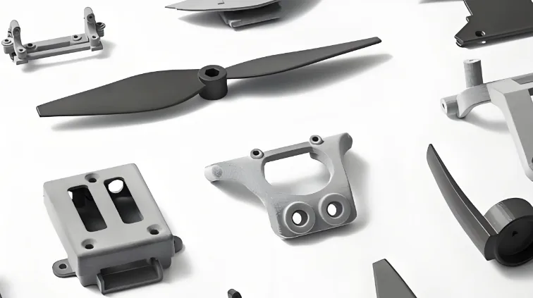
Precision Milling for UAV Housings: Materials, GD&T, Sealing Surfaces, 5‑Axis Strategies, Inspection Plans, and 3 Case Studies (JLYPT CNC Machining)
UAV housings are where aerodynamics meets electronics, vibration meets sealing, and mass targets collide with manufacturability. Unlike many “box-like” machined enclosures, drone housings tend to be compact, lightweight, thermally constrained, and subjected to continuous vibration, occasional hard landings, and frequent maintenance cycles. A housing that looks simple on a CAD screen can become the single biggest driver of assembly yield problems if its datums drift, its sealing faces warp, or its threaded features strip after repeated service.
That’s why Precision milling for UAV housings should be approached as a system: geometry + material + finish + fixturing + inspection. You’re not only cutting a shape, you’re building a stable reference structure for a flight-critical assembly.
This long-form guide shares practical, production-oriented methods used in CNC machining to manufacture UAV housings with consistent fit-up, predictable sealing, repeatable positional accuracy, and finishes that survive real missions.
If you’re sourcing machined UAV parts and want a supplier who can support prototype-to-production workflows, JLYPT’s custom UAV machining capability is here:
Custom CNC UAV Parts Manufacturer
Buying the airframe as a package instead of one bracket at a time changes what belongs on the drawing. custom UAV parts starts there.
Table of Contents
- What Counts as a “UAV Housing” (and Why It’s Hard to Machine Well)
- Precision Milling for UAV Housings: The Functional Requirements That Matter
- Typical Housing Architectures (Electronics Enclosure, Gimbal, Motor Mount, Payload Bay)
- Material Selection: Aluminum, Magnesium, Stainless, Titanium, Engineering Plastics
- Finishes and Coatings: Anodize, Chem Film, Passivation, Conductive Coatings
- Datum Strategy & GD&T: Building a Housing That Assembles Without Stress
- Fixturing for Accuracy and Thin-Wall Stability (Soft Jaws, Vacuum, Zero-Point)
- 3‑Axis vs 4‑Axis vs 5‑Axis Milling: Choosing the Right Setup Strategy
- Tooling and Toolpaths: HSM, Adaptive Clearing, Tool Deflection, Chatter Control
- Sealing Surfaces and O‑Ring Grooves: Flatness, Compression, and Leak Risk
- Thermal Management Features: Heat Paths, Interface Flatness, Fin Arrays
- Threads, Inserts, and Reamed Holes: Serviceability Without Stripping
- Weight Reduction Pocketing Without Warping the Part
- Inspection Plans: Probing, CMM, Surface Plate, and Functional Gauging
- Cost Drivers + RFQ Checklist (Detailed Tables Included)
- Three Case Studies
- Why JLYPT for Precision Milling for UAV Housings + How to Start
- External References (DoFollow Links)
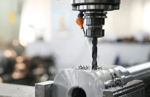
1) What Counts as a “UAV Housing” (and Why It’s Hard to Machine Well)
In practice, “UAV housing” can mean any structural enclosure or body that locates, protects, and interfaces with subsystems such as:
- flight controller / autopilot enclosure
- power distribution and ESC housing
- camera and gimbal body
- RF/telemetry module enclosure
- payload bay housing
- motor mount housing or integrated arm-housing junction
- battery lock housing
- environmental sensor housing (barometer, lidar modules, etc.)
These parts often share three manufacturing realities:
- They are datum-driven.
A housing becomes the “master reference” for other components. If its datums are inconsistent, your assembly becomes a tolerance stack-up problem. - They are finish-sensitive.
Anodizing, chem film, conductive coatings, or paint can change dimensions and surface properties. A good design and process route anticipates coating growth and masking. - They are stability-sensitive.
UAV housings frequently include thin walls, deep pockets, and large material removal ratios. Those conditions amplify residual stress release, clamping distortion, and thermal drift.
That combination is precisely why Precision milling for UAV housings is not only about reaching nominal dimensions, it’s about ensuring the part behaves predictably during assembly and in flight.
2) Precision Milling for UAV Housings: The Functional Requirements That Matter
A successful UAV housing is defined by functional performance, not by a list of tolerances. Before choosing a machining strategy, it helps to identify which characteristics are truly critical-to-quality (CTQ).
Table 1 , Functional Requirements and Their Real-World Impact
| Functional requirement | What it affects | Typical CTQ features |
|---|---|---|
| Assembly alignment | connector engagement, board fit, lens alignment | datum planes, hole patterns, pocket locations |
| Sealing performance | IP rating, dust ingress, condensation | O-ring grooves, sealing face flatness, gasket compression |
| Vibration survivability | connector fretting, fastener loosening | thread quality, insert pull-out strength, rib stiffness |
| Thermal control | component temperature and throttling | interface flatness for heat spreaders, fin geometry |
| EMI/EMC behavior | signal integrity, RF noise | grounding pads, conductive coating prep, bonding surfaces |
| Serviceability | maintenance time and stripped threads | thread engagement depth, insert selection, tool access |
| Weight efficiency | flight time and payload | pocketing strategy, wall thickness, topology constraints |
For most UAV housings, the “precision” portion of Precision milling for UAV housings typically centers on:
- positional accuracy of hole patterns and pockets
- flatness and parallelism on sealing and interface faces
- perpendicularity between mating planes
- surface finish on sealing faces and thermal interfaces
- repeatability across batches (so assemblies don’t need hand-fitting)
3) Typical Housing Architectures (What You’re Really Milling)
3.1 Two-piece clamshell enclosures
Common for electronics: base + lid, gasket or O-ring between them, fasteners around the perimeter.
3.2 Monoblock housings with internal pockets
Used when rigidity is critical or when you want fewer sealing joints.
3.3 Split housings with precision bores
Typical for gimbals and rotating assemblies where bearings and shafts must be aligned.
3.4 Hybrid housings
Machined metal chassis with polymer covers, or metal inserts co-molded into plastic.
Table 2 , Housing Type vs Machining Implications
| Housing type | Strengths | Machining challenges | Typical process notes |
|---|---|---|---|
| Clamshell (lid + base) | easy access, serviceable | sealing face flatness + alignment | machine sealing datum in one setup where possible |
| Monoblock pocketed | stiff, fewer seals | high material removal, distortion | staged roughing + stress relief planning |
| Bearing/bores housing | alignment critical | coaxiality, reamed bores | consider 4/5-axis to keep bores referenced |
| Hybrid (metal + polymer) | weight and RF benefits | interface tolerances | design inserts and datum interfaces intentionally |
4) Material Selection for Precision Milled UAV Housings
Material selection is a balancing act: mass, stiffness, thermal conductivity, corrosion behavior, coating compatibility, and machinability.
Common choices:
- 6061‑T6 aluminum: stable, cost-effective, good anodizing behavior
- 7075‑T6 aluminum: higher strength, excellent for structural housings
- 2024 aluminum: high fatigue strength, but corrosion considerations
- Magnesium alloys: very light, special handling and finishing requirements
- Stainless steel: durable but heavy; used for harsh environments or wear surfaces
- Titanium: high strength-to-weight but expensive and slower to machine
- Engineering plastics (PEEK, Delrin/Acetal, Nylon): lightweight, RF-transparent, but creep and thermal expansion must be managed
Table 3 , Material Comparison for UAV Housings (Machining-Oriented)
| Material | Density | Relative machinability | Corrosion resistance | Best-fit housing use cases |
|---|---|---|---|---|
| 6061‑T6 Al | low | excellent | good | general enclosures, prototypes, most UAV electronics housings |
| 7075‑T6 Al | low | very good | fair-good with anodize | structural housings, motor mounts, high-load frames |
| 2024 Al | low | good | moderate | fatigue-driven structures with controlled environment |
| Magnesium | very low | good (with controls) | needs protection | extreme weight optimization programs |
| 304/316 SS | high | moderate | very good | corrosive environments, ruggedized housings |
| Ti‑6Al‑4V | medium | challenging | excellent | high-end weight/strength targets, harsh thermal profiles |
| PEEK | very low | good | excellent | RF windows, weight-critical covers, chemical exposure |
| Acetal (Delrin) | very low | excellent | good | non-structural covers, fixtures, prototypes |
In Precision milling for UAV housings, aluminum alloys dominate because they offer an excellent compromise between stiffness, weight, thermal performance, machinability, and finishing options.
5) Finishes and Coatings: Plan Them Before You Cut Metal
Finishing is not an afterthought; it changes dimensions, affects conductivity, and can make or break sealing performance.
Common finishing options for UAV housings:
- Type II anodizing (decorative/protective)
- Type III hard anodizing (wear resistance; thicker; more dimensional impact)
- Chromate conversion / chem film (conductive corrosion protection, common for bonding/grounding)
- Passivation (for stainless)
- Powder coat / paint (cosmetic, corrosion protection; impacts tolerances)
- Conductive coatings (EMI shielding; often used on polymer housings, sometimes on metal)
Table 4 , Finish Selection and Dimensional Considerations
| Finish | Primary purpose | Dimensional impact | Manufacturing note |
|---|---|---|---|
| Type II anodize | corrosion, appearance | low-moderate | consider masking for ground pads |
| Type III anodize | wear resistance | moderate-high | plan tolerance and masking carefully |
| Chem film | conductive corrosion protection | very low | good for grounding surfaces |
| Passivation | stainless corrosion resistance | negligible | keep surfaces clean; avoid embedded iron |
| Paint/powder | cosmetic/environmental | high variability | avoid on precision mating surfaces |
If your design includes press fits, tight pocket fits, or sealing faces, explicitly define whether those surfaces are:
- masked (no coating)
- coated (and tolerance adjusted)
- post-finished (e.g., lap/face after coating, rare, but possible)
6) Datum Strategy & GD&T: The Backbone of Precision Milling for UAV Housings
Most assembly problems trace back to a weak datum strategy. A UAV housing should be dimensioned so the CNC process can reference the same functional surfaces that your assembly references.
6.1 Recommended datum hierarchy (typical)
- Datum A: primary mounting plane (the interface face to frame or lid)
- Datum B: secondary orthogonal face or locating feature
- Datum C: tertiary face or a precision dowel/reamed hole
6.2 GD&T controls that typically matter
- Flatness on sealing face and heat spreader interface
- Parallelism between lid and base planes
- Position of hole patterns for boards, standoffs, connectors
- Perpendicularity between side walls and datum plane
- Profile of surface for critical external forms or aerodynamic interfaces
Table 5 , GD&T Cheatsheet for UAV Housing CTQs
| Housing feature | GD&T control commonly used | Why it’s effective |
|---|---|---|
| sealing face | flatness (and sometimes surface finish callout) | leak prevention and gasket compression consistency |
| lid-to-base interface | parallelism between datum planes | prevents twist and uneven compression |
| connector cutouts | profile of surface | maintains functional clearance and sealing geometry |
| PCB standoff pattern | position to datums | ensures board alignment and connector mate |
| dowel holes | position + tight size (ream) | repeatable assembly registration |
| bearing/shaft bores (gimbal) | position/coaxiality as needed | smooth rotation, low friction |
A strong print makes Precision milling for UAV housings more predictable because the machinist can tie toolpaths, probing routines, and inspection directly to functional datums.
7) Fixturing for Accuracy and Thin‑Wall Stability
Fixturing is where “precision” becomes real. Many UAV housings are thin-walled and pocketed, so you must control clamping distortion and maintain repeatable location.
Common fixturing methods
- Custom soft jaws (machined to match the part’s external geometry)
- Vacuum fixtures (excellent for flat parts and lids; needs leak-safe design)
- Zero-point workholding (repeatable changeover; good for multiple setups)
- Modular fixturing plates with dowels and stops
- Dedicated tombstones for 4-axis production
Table 6 , Fixturing Options and When to Use Them
| Fixture method | Best for | Advantages | Watch-outs |
|---|---|---|---|
| Soft jaws | irregular housings | strong location repeatability | jaw wear; must control clamp force |
| Vacuum | lids, plates, shallow parts | minimal distortion | leaks, limited cutting forces |
| Zero-point | multi-setup workflow | repeatable, fast | upfront system cost |
| Modular plate + dowels | prototypes to low volume | flexible | setup discipline required |
| 4-axis tombstone | volume housings | throughput, consistency | requires stable process and program maturity |
For Precision milling for UAV housings, the goal is not maximum clamping force, it’s consistent location with minimum elastic deformation.
8) 3‑Axis vs 4‑Axis vs 5‑Axis Milling: Choosing the Right Strategy
A key decision in housing manufacturing is the number of setups. Every time you re-clamp a part, you introduce risk: datum shift, accumulated tolerance, and cosmetic damage.
8.1 3-axis machining
Best for simpler housings with most features accessible from one or two sides.
8.2 4-axis machining (indexing)
Excellent for housings with features around the perimeter: connector windows, side mounting patterns, side pockets.
8.3 5-axis machining
Often ideal for:
- reducing setup count
- keeping critical features referenced to one datum system
- accessing angled features and internal geometries
- improving positional accuracy for complex housings and gimbal bodies
Table 7 , Setup Strategy vs Risk and Capability
| Strategy | Typical setup count | Pros | Cons |
|---|---|---|---|
| 3-axis (2–3 setups) | 2–3 | cost-effective | higher re-clamp risk |
| 4-axis indexing | 1–2 | great for perimeter features | requires rotary calibration |
| 5-axis | 1–2 | best access + datum integrity | programming/fixturing complexity |
If your housing contains both a sealing system and precision alignment features (e.g., dowel holes + connector openings + heat spreader face), 4/5-axis strategies frequently reduce cumulative error and improve assembly yield, core benefits of Precision milling for UAV housings.
9) Tooling and Toolpaths: HSM, Deflection, and Chatter Control
Housing machining typically involves:
- deep pocketing
- long-reach tools
- thin walls
- cosmetic surfaces
That’s a perfect recipe for chatter and dimensional drift if toolpaths are not optimized.
9.1 High-speed machining (HSM) principles used in housings
- adaptive clearing for roughing (constant engagement)
- step-down/step-over tuned for rigidity
- climb milling for better surface finish
- rest machining for consistent stock removal
- finishing passes with consistent tool load
9.2 Tool deflection and thin walls
A thin wall can “move away” from the cutter and spring back after machining, resulting in undersized pockets or out-of-flat faces.
Mitigations:
- leave uniform stock for finishing
- use sharp tools and reduce radial engagement
- add temporary ribs / tabs (when design allows)
- sequence operations to maintain stiffness as long as possible
- minimize dwell and heat input on finishing passes
Table 8 , Common Milling Problems in UAV Housings (and Fixes)
| Problem | What it looks like | Likely cause | Practical fix |
|---|---|---|---|
| wall taper | pocket wider at top | tool deflection | reduce engagement; finish with spring pass |
| chatter marks | ripples on walls | resonance + long reach | adjust RPM/feed; shorten stick-out; toolpath change |
| warped sealing face | leaks, uneven gap | residual stress + clamping | staged roughing; reduce clamp force; face last |
| poor hole position | assembly misfit | re-clamp shift | probe datums; reduce setups; use dowel-based fixture |
| burrs on edges | gasket damage | dull tool / poor deburr plan | specify edge break; controlled deburr process |
When customers ask what makes Precision milling for UAV housings “precision,” it’s often this: disciplined toolpath planning plus fixturing that preserves the part’s intended geometry.
10) Sealing Surfaces and O‑Ring Grooves: Flatness, Compression, and Leak Risk
Sealing is one of the most common failure points in UAV housings, especially in humid, dusty, or coastal environments.
10.1 Sealing face requirements
Sealing faces should be:
- flat enough to ensure uniform compression
- smooth enough to avoid micro leak paths
- protected from nicks during handling and assembly
10.2 O-ring groove machining
O-ring grooves require careful control of:
- groove width and depth
- corner radii (avoid cutting the O-ring)
- surface finish in groove base
- lead-in chamfers at assembly points
Table 9 , Sealing Feature Checklist (Machining + Design)
| Sealing element | Key machining control | Why it matters |
|---|---|---|
| sealing face | flatness + surface finish | determines leak path risk |
| groove depth | tight depth control | sets compression ratio |
| groove width | consistent width | prevents pinch or extrusion |
| groove corners | defined radius | avoids O-ring damage |
| fastener pattern | even spacing | uniform compression distribution |
10.3 Practical manufacturing note: finish the sealing face late
Where possible, machine (or skim) the sealing face near the end of the process route to reduce the chance that later clamping, aggressive roughing, or thermal load will distort it.
This is a signature practice in Precision milling for UAV housings intended for environmental sealing.
11) Thermal Management Features: Heat Paths, Interface Flatness, Fin Arrays
UAV electronics can be thermally constrained: compact packaging, limited airflow, and solar loading. Housings frequently act as heat spreaders.
Common thermal features:
- flat interface pads for thermal gap filler
- heat sink fins
- thickened bosses under high-power components
- thermal “bridges” to external surfaces
Table 10 , Thermal Feature Machining Considerations
| Thermal feature | Machining challenge | Recommended approach |
|---|---|---|
| interface pad | flatness + finish | face with stable toolpath; verify on surface plate |
| fin arrays | thin fin chatter | use proper tool and step-over; avoid aggressive engagement |
| thick bosses | local residual stress | rough symmetrically; finish after stabilization |
| embedded channels | tool access | consider 5-axis or split housing design |
Thermal pads typically require controlled flatness and a consistent surface texture; both are directly influenced by cutter choice, toolpath direction, and machine thermal stability, core details in Precision milling for UAV housings.
12) Threads, Inserts, and Reamed Holes: Serviceability Without Stripping
UAV housings are often opened repeatedly for maintenance. That means:
- thread durability matters
- fastener access matters
- insert strategy matters
12.1 Thread manufacturing options
- Tapping: fast, common; can be risky in hard anodize or small threads if not controlled
- Thread milling: excellent for tough materials and controlled threads; good for blind holes with chips managed
- Form tapping (where applicable): stronger threads in ductile materials, no chips
12.2 Inserts
Common insert choices:
- wire thread inserts (e.g., helicoil-style)
- key-locking inserts
- press-fit / heat-set inserts (especially in plastics)
12.3 Precision holes
Reamed holes and dowel holes are often used as assembly datums. They should be machined in a stable setup and referenced to the same datums used for the rest of the housing.
Table 11 , Thread and Hole Feature Guide for UAV Housings
| Feature | Recommended method | Why |
|---|---|---|
| small threads (M2–M4) | thread mill or controlled tapping | consistent thread quality, reduced breakage risk |
| serviceable aluminum threads | inserts where repeated cycles occur | prevents stripping |
| alignment dowels | drill + ream in same setup | improves positional repeatability |
| bearing seats/bores | boring/reaming + inspection | geometry control and smoother rotation |
13) Weight Reduction Pocketing Without Warping the Part
Weight reduction is important, but aggressive pocketing can cause:
- wall “oil-canning”
- distorted sealing faces
- poor positional accuracy after unclamping
- vibration-amplifying flexible panels
Manufacturing-focused design strategies:
- maintain minimum wall thickness appropriate to the material and part size
- add ribs and gussets rather than thinning everything uniformly
- avoid large unsupported flat panels when possible
- stage roughing to reduce residual stress
Table 12 , Pocketing Strategies That Preserve Stability
| Approach | Benefit | Trade-off |
|---|---|---|
| leave stock for finish | improves dimensional control | extra cycle time |
| symmetric material removal | reduces warp | requires planning |
| rib-based stiffness | keeps weight low but stiff | may complicate tool access |
| larger internal radii | improves tool life and stress distribution | may reduce usable volume slightly |
In Precision milling for UAV housings, “lightweight” is not only a mass number, it’s stiffness, stability, and repeatable geometry across production.
14) Inspection Plans: Probing, CMM, Surface Plate, and Functional Gauging
A proper inspection plan ties directly to functional datums and CTQs.
14.1 In-process probing
On-machine probing can:
- set and verify work offsets
- detect setup drift
- check critical hole positions before removing the part
- reduce scrap in multi-setup workflows
14.2 CMM and form measurement
For complex housings, a CMM can validate:
- positional tolerance patterns
- profile of surfaces
- datums and perpendicularity relationships
14.3 Surface plate checks
Sealing faces and thermal pads often benefit from:
- surface plate + height gauge checks
- flatness verification using appropriate methods for your tolerance level
Table 13 , Inspection Method vs CTQ
| CTQ | Best inspection tool | Notes |
|---|---|---|
| hole pattern position | CMM or functional gauge | ensure correct datum alignment |
| sealing face flatness | surface plate method / CMM plane | protect surface during inspection |
| pocket depth | depth mic / CMM | verify where board clearance is tight |
| thread quality | go/no-go gauges | especially for production |
| coating thickness (if critical) | coating thickness gauge | coordinate with finish vendor |
Good suppliers of Precision milling for UAV housings do not “inspect everything equally.” They align inspection effort with the features that actually drive assembly success and field reliability.
15) Cost Drivers + RFQ Checklist (Detailed Tables Included)
15.1 Major cost drivers
- number of setups and re-clamps
- 5-axis programming complexity
- tight positional tolerances across large patterns
- flatness requirements on large sealing faces
- deep pockets and thin walls (slower feeds, more finishing passes)
- high cosmetic requirements (tool mark limits, bead blasting + anodize consistency)
- inspection reporting requirements (FAI, CMM reports)
Table 14 , Cost Driver Map (What Changes Price Fast)
| Requirement | Why it costs more | Typical mitigation |
|---|---|---|
| ultra-tight position tolerance | requires better fixturing + inspection | add dowel datums; reduce setups |
| tight flatness on large face | needs stable machining + verification | finish face last; manage clamping |
| thin walls + deep pockets | increases cycle time and risk | staged roughing + rib strategy |
| hard anodize on precision fits | coating growth affects sizes | mask or adjust tolerances |
| high cosmetic standard | extra finishing and handling | define cosmetic zones on drawing |
15.2 RFQ checklist (send this to reduce iterations)
Table 15 , RFQ Checklist for Precision Milling for UAV Housings
| Item | What to provide | Why it matters |
|---|---|---|
| 3D model | STEP preferred | speeds CAM planning |
| 2D drawing | GD&T + datums + notes | defines inspection and CTQs |
| material | alloy + condition | impacts toolpath, cost, finish compatibility |
| finish | anodize/chem film/passivation + color | affects dimensions and masking |
| sealing requirements | gasket/O-ring type, IP target if available | influences surface and groove controls |
| quantity | prototype + planned batch sizes | impacts fixture and process choice |
| hardware | inserts, fasteners, dowels | determines secondary ops |
| inspection | FAI, CMM report, sampling plan | sets QA effort and lead time |
| packaging | protect sealing faces and cosmetic areas | prevents shipping damage |
16) Three Case Studies (Production-Style Scenarios)
The cases below are written in an engineering style so you can reuse the logic for your own DFM and sourcing decisions.
Case Study 1 , Sealed Flight-Controller Enclosure with O-Ring Groove and Connector Windows
Part type: Two-piece UAV electronics housing (base + lid)
Primary constraints: IP-style sealing, multiple side connector cutouts, compact internal cavity for stacked PCBs
Manufacturing risks identified
- sealing face flatness drift after aggressive pocketing
- burrs and edge damage around connector windows (risk to gaskets and harnesses)
- coating strategy conflicts: anodize desired for corrosion, but ground pads must remain conductive
Process strategy
- establish Datum A on the sealing face early, but final skim the sealing face late
- rough pocketing with adaptive clearing, leaving uniform stock for finishing passes
- machine connector windows with a controlled finishing toolpath to reduce burr formation
- define masking regions for grounding pads and critical fits before anodizing
- add a controlled edge-break spec to protect O-rings and cable jackets
Outcome Assembly torque became more consistent (fasteners seated evenly), and leak-risk reduced because sealing compression became uniform across the perimeter, exactly the type of result customers expect from Precision milling for UAV housings with sealing requirements.
Case Study 2 , 5-Axis Gimbal Camera Housing with Bearing Bores and Tight Positional Relationships
Part type: Gimbal housing body with multiple angled faces and precision bores
Primary constraints: bearing alignment, smooth rotation, low friction, minimal imbalance
Manufacturing risks identified
- accumulated error from multiple re-clamps (bores and mounting faces drifting relative to each other)
- tool access limitations causing long tool stick-out and chatter
- cosmetic requirements for anodized exterior
Process strategy
- use a 5-axis strategy to reduce setups and keep key features referenced to one datum structure
- bore critical diameters in a stable orientation after roughing, then finish with controlled tool engagement
- specify inspection tied to datums: bore position, perpendicularity to mounting face, and interface flatness
- protect cosmetic surfaces via fixture contact planning and controlled handling
Outcome Fewer setups reduced positional scatter, and bore alignment improved. The gimbal assembly required less manual adjustment, and rotation feel became consistent across builds, another concrete benefit of Precision milling for UAV housings using 5-axis methods.
Case Study 3 , Lightweight Power Module Housing with Thin Walls, Heat-Sink Fins, and Inserted Threads
Part type: Power electronics housing with integrated fins and serviceable threaded locations
Primary constraints: mass reduction, thermal performance, repeated maintenance cycles
Manufacturing risks identified
- thin-wall deformation during clamping and finishing
- fin chatter and inconsistent fin thickness
- thread wear in aluminum during repeated opening cycles
Process strategy
- staged roughing to maintain stiffness; finish thin walls late
- fin machining using a stable toolpath strategy and tuned cutting parameters to prevent chatter marks
- thread milling on critical threads + planned insert locations for repeated service areas
- inspection emphasis on thermal pad flatness and fin geometry consistency
Outcome Thermal interface pads held flatness better, fin surfaces were more consistent after anodizing, and service threads resisted wear because inserts were placed where maintenance cycles were highest, practical, field-driven results that define serious Precision milling for UAV housings.
17) Why JLYPT for Precision Milling for UAV Housings + How to Start
Precision housings require more than machine time. They require process thinking: datum control, setup reduction, deformation management, finish planning, and inspection that matches your functional requirements.
JLYPT CNC Machining supports custom UAV parts manufacturing, from prototype enclosures to batch production housings, with CNC milling strategies aligned to aerospace-style expectations: stable references, controlled interfaces, and clear documentation where needed.
Start your project here :
Custom CNC UAV Parts Manufacturer
Homepage :
JLYPT
To get an accurate quotation faster, send:
- STEP + 2D drawing with datums and GD&T
- material and finish requirements (including masking zones if applicable)
- target quantity (prototype + expected batches)
- CTQ list (sealing face flatness, hole pattern position, thermal pad flatness, etc.)
- any assembly notes (dowel usage, gasket type, torque specs if available)