
Drone Arm Clamps CNC Machining: Engineering Precision for Next-Generation UAV Systems
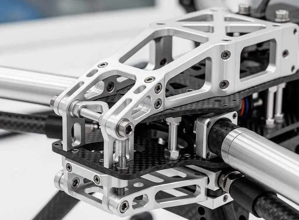
The structural integrity of unmanned aerial vehicles fundamentally depends on the mechanical performance of drone arm clamps, which serve as critical load-bearing interfaces between motor mounts, carbon fiber tubes, and central body frames. At JLYPT CNC Machining, we engineer drone arm clamps through advanced subtractive manufacturing processes that deliver dimensional accuracy within ±0.005mm, surface roughness values below Ra 0.8μm, and material properties optimized for cyclic loading conditions encountered during flight operations.
Our drone arm clamps CNC machining capabilities span from rapid prototyping of experimental UAV designs to volume production of certified aerospace components, utilizing multi-axis milling centers, Swiss-type turning equipment, and wire EDM systems. This comprehensive manufacturing approach addresses the unique challenges of drone component fabrication: achieving minimal weight while maintaining structural rigidity, creating complex geometries that facilitate tool-free assembly, and ensuring repeatability across production batches that meet AS9100 quality standards.
Understanding Drone Arm Clamp Design Requirements
Drone arm clamps function as mechanical couplers that must simultaneously resist bending moments generated by propeller thrust, absorb vibration frequencies ranging from 80Hz to 400Hz produced by brushless motors, and maintain positional accuracy under thermal expansion cycles. The engineering specifications for these components typically mandate tensile strength exceeding 900 MPa, fatigue life beyond 10^6 cycles at operational stress levels, and weight optimization that reduces each clamp assembly to under 15 grams for commercial multirotor platforms.
Material selection directly impacts both machining strategy and end-use performance. Aluminum alloys 7075-T6 and 6061-T6 dominate commercial drone applications due to their strength-to-weight ratio of approximately 196 kN·m/kg, while aerospace-grade titanium Ti-6Al-4V becomes necessary for high-performance racing drones and industrial inspection platforms where operating temperatures exceed 150°C. Carbon fiber reinforced polymer clamps require entirely different fabrication methods involving composite layup rather than CNC machining, though hybrid designs increasingly incorporate machined aluminum inserts bonded into CFRP structures.
The geometric complexity of modern drone arm clamps has evolved significantly beyond simple cylindrical collars. Contemporary designs feature integrated cable routing channels with 2mm wall thicknesses, asymmetric clamping surfaces that distribute pressure across 270-degree contact arcs, and threaded mounting bosses positioned at compound angles to accommodate motor cant angles between 3 and 8 degrees. These features demand 5-axis simultaneous machining capabilities to achieve proper surface finish on all functional faces without requiring multiple setups that introduce tolerance stack-up errors.
CNC Machining Processes for Drone Arm Clamp Production
Multi-Axis Milling Operations
Five-axis CNC milling represents the primary fabrication method for drone arm clamps due to its ability to machine complex contours in single setups while maintaining tight geometric tolerances. Our Haas UMC-750 and DMG MORI DMU 50 machining centers execute toolpaths that approach workpieces from continuously variable angles, enabling the creation of undercut features, compound-angle mounting holes, and organic blend radii that optimize stress distribution around high-load attachment points.
The typical machining sequence begins with face milling operations using indexable carbide cutters to establish primary datum surfaces, followed by roughing passes with 6mm ball-end mills that remove bulk material at feed rates approaching 2000mm/min. Semi-finishing operations employ 3mm radius tools with 0.2mm stepover distances to achieve surface profiles within 0.05mm of nominal geometry, while final finishing passes utilize 1mm ball-nose end mills at 15,000 RPM spindle speeds to generate Ra 0.4μm surface textures on clamping interfaces.
Tool selection critically affects both production efficiency and part quality. For aluminum drone arm clamps, we deploy AlTiN-coated solid carbide end mills with 35-degree helix angles that provide excellent chip evacuation in the shallow slot geometries characteristic of cable routing channels. Titanium alloy components require more conservative cutting parameters—typically 40-50 m/min surface speeds compared to 200-300 m/min for aluminum—and benefit from through-spindle coolant delivery at 70 bar pressure to manage the material’s poor thermal conductivity and tendency toward work hardening.
Precision Turning for Cylindrical Features
Swiss-type CNC lathes excel at producing drone arm clamps with primary cylindrical geometries, particularly designs that clamp onto carbon fiber tubes through radial compression. The Star SR-20R II sliding-headstock lathe in our facility machines these components from bar stock with live tooling capabilities that add cross-holes, flats, and threaded features without secondary operations.
The process begins with main spindle operations that turn the outer diameter to within 0.01mm of final dimension, followed by sub-spindle transfer and backworking that completes the opposite end face. Live tooling stations then execute milling operations for mounting holes, wrench flats, and set screw pockets while the part remains fixtured in the collet, eliminating positional errors associated with part rehandling. This single-setup approach proves particularly valuable for small-diameter clamps under 25mm where workholding becomes challenging in conventional machining centers.
Thread milling operations for M3 and M4 mounting screws utilize helical interpolation rather than tapping to achieve better thread quality and eliminate tap breakage risks in the thin-walled sections typical of lightweight drone components. Our thread milling strategy employs single-flute carbide mills that generate UN and ISO metric threads with 6H tolerance class, ensuring proper engagement with hardened steel fasteners while maintaining minimum wall thickness of 1.2mm around threaded bosses.
Wire EDM for Complex Profiles
Electrical discharge machining becomes necessary when drone arm clamp designs incorporate features impossible to access with rotating cutting tools—internal pockets with sharp corners, through-slots narrower than available end mill diameters, or hardened tool steel inserts that resist conventional machining. Our Mitsubishi MV2400R wire EDM system cuts these features using 0.25mm brass wire at removal rates approaching 300 mm²/min in aluminum alloys.
The EDM process proves especially valuable for creating the split-line geometries in two-piece clamp designs, where precision gaps of 0.15-0.20mm must be maintained to ensure proper compression when tightening fasteners. Wire EDM achieves these critical dimensions with positional accuracy of ±0.003mm while producing burr-free edges that eliminate secondary deburring operations. The thermal nature of EDM also creates a thin recast layer approximately 5-8μm deep that can be removed through subsequent bead blasting if required for fatigue-critical applications.
Material Specifications and Selection Criteria
| Material Grade | Tensile Strength | Density | Thermal Expansion | Machinability Rating | Typical Applications |
|---|---|---|---|---|---|
| Aluminum 6061-T6 | 310 MPa | 2.70 g/cm³ | 23.6 μm/m·K | 90/100 | Consumer drones, educational UAVs, recreational multirotors |
| Aluminum 7075-T6 | 572 MPa | 2.81 g/cm³ | 23.2 μm/m·K | 70/100 | Racing drones, high-performance photography platforms, competition UAVs |
| Titanium Ti-6Al-4V | 950 MPa | 4.43 g/cm³ | 8.6 μm/m·K | 45/100 | Aerospace inspection drones, military UAVs, extreme environment applications |
| Stainless 17-4 PH | 1310 MPa | 7.75 g/cm³ | 10.8 μm/m·K | 55/100 | Corrosive environment drones, marine survey platforms, chemical plant inspection |
| Magnesium AZ31B | 260 MPa | 1.78 g/cm³ | 26.0 μm/m·K | 85/100 | Ultra-lightweight racing drones, long-endurance surveillance platforms |
Aluminum 6061-T6 serves as the workhorse material for commercial drone arm clamps due to its optimal balance of mechanical properties, cost-effectiveness, and machining efficiency. The alloy’s excellent weldability allows for hybrid manufacturing approaches where CNC-machined clamp bodies integrate with TIG-welded mounting tabs, though such designs require post-weld heat treatment to restore T6 temper properties. The material machines cleanly at high feed rates, typically generating continuous chips rather than the segmented chips characteristic of higher-silicon casting alloys, which simplifies chip management in high-volume production environments.
For applications demanding maximum strength-to-weight performance, 7075-T6 aluminum provides nearly double the tensile strength of 6061 while adding only 4% additional weight. This alloy contains zinc as the primary alloying element rather than magnesium, creating precipitation-hardened microstructures that achieve yield strengths approaching 500 MPa. The trade-off involves reduced machinability—cutting forces increase by approximately 30% compared to 6061, and tool wear accelerates due to the alloy’s higher hardness. We compensate through optimized tooling strategies including PVD-coated end mills and reduced depth-of-cut parameters that maintain tool life above 200 parts per cutting edge.
Titanium Ti-6Al-4V enters the specification when operating conditions exceed aluminum’s capabilities, particularly in high-temperature environments or applications requiring superior fatigue resistance under variable amplitude loading. The material’s low thermal conductivity (7.0 W/m·K versus 130 W/m·K for aluminum) creates significant machining challenges, as heat concentrates at the cutting edge rather than dissipating through the workpiece. Our titanium machining protocols employ flood coolant at 80 bar pressure, conservative cutting speeds below 50 m/min, and frequent tool indexing to prevent edge breakdown. Despite these challenges, titanium drone arm clamps achieve service lives 3-5 times longer than aluminum equivalents in abrasive or corrosive environments.
Design for Manufacturability Considerations
The transition from CAD model to production-ready drone arm clamp requires careful analysis of geometric features to ensure manufacturability without compromising functional requirements. Sharp internal corners represent a common design pitfall—while FEA software may show acceptable stress concentrations at 90-degree corners, CNC end mills cannot produce true sharp corners due to their circular cross-sections. We recommend minimum corner radii of 0.5mm for non-critical features and 1.0mm for high-stress areas, which accommodates standard tooling while providing stress relief benefits that extend fatigue life.
Wall thickness uniformity significantly impacts both machining stability and part performance. Sections thinner than 0.8mm exhibit excessive deflection during cutting operations, leading to dimensional inaccuracy and surface finish degradation. Our design guidelines specify 1.2mm minimum wall thickness for aluminum clamps and 1.5mm for titanium to ensure adequate rigidity during machining while maintaining structural integrity under operational loads. Thicker sections approaching 5-6mm should incorporate lightening pockets or organic topology-optimized geometries to reduce weight without creating the vibration-prone thin-wall conditions that complicate machining.
Tolerance specification must balance functional requirements against manufacturing cost. Hole-to-hole positional tolerances tighter than ±0.05mm typically require secondary operations such as jig boring or precision reaming, adding 40-60% to production costs. We work with design engineers to identify truly critical dimensions—usually mounting hole patterns and clamping surface diameters—while relaxing tolerances on non-functional features to ±0.1mm or wider. This selective tolerance approach maintains assembly performance while enabling efficient machining strategies that minimize setup time and inspection requirements.
Surface Treatment and Finishing Operations
Anodizing for Aluminum Components
Type II sulfuric acid anodizing creates a 10-25μm thick aluminum oxide layer on drone arm clamps that provides both corrosion resistance and wear protection for threaded features. The anodizing process converts the surface aluminum into a porous ceramic structure through electrochemical oxidation, which we then seal through hot water immersion to close surface pores and enhance corrosion resistance. Color anodizing options allow for component identification in complex UAV assemblies, with black, red, blue, and gold being standard offerings that add no measurable weight to finished parts.
Hard anodizing (Type III) generates coating thicknesses approaching 50-75μm with surface hardness values reaching 400-500 HV, comparable to tool steels. This treatment proves essential for drone arm clamps subjected to frequent assembly/disassembly cycles, as the hard oxide layer prevents galling and thread damage during repeated fastener installation. The process does introduce dimensional changes—coating builds up approximately 50% outward and 50% inward from the original surface—requiring that critical dimensions be machined 0.025-0.038mm oversize to achieve final tolerances after anodizing.
Passivation and Electropolishing for Stainless Steel
Stainless steel drone arm clamps require passivation treatment to remove free iron contamination introduced during machining and restore the chromium oxide passive layer that provides corrosion resistance. Our citric acid passivation process (per AMS 2700) treats components for 20-30 minutes at 49-60°C, dissolving embedded iron particles without attacking the base stainless steel. This treatment proves critical for marine environment drones where salt spray exposure would otherwise initiate pitting corrosion at machining-disturbed surfaces.
Electropolishing removes 10-30μm of surface material through controlled anodic dissolution, simultaneously improving corrosion resistance and reducing surface roughness to Ra 0.2μm or better. The process preferentially attacks peaks in the surface topography while leaving valleys relatively unchanged, creating a microscopically smooth finish that reduces drag in airflow and prevents particle accumulation in cable routing channels. For precision drone arm clamps, electropolishing also removes the mechanically disturbed surface layer created by machining, potentially improving fatigue performance by 15-20% compared to as-machined conditions.
Bead Blasting and Media Finishing
Glass bead blasting using 100-170 mesh beads at 40-60 PSI pressure creates uniform matte surfaces on drone arm clamps while removing machining marks, minor burrs, and oxide discoloration. The process generates compressive residual stresses in the surface layer—typically 50-100 MPa—that can enhance fatigue resistance in high-cycle loading applications. We carefully control blasting parameters to avoid excessive material removal or surface roughening that would compromise dimensional tolerances, typically limiting treatment to non-critical external faces while masking precision mounting surfaces.
Vibratory finishing in ceramic media provides an automated deburring solution for high-volume drone arm clamp production, processing batches of 50-100 parts simultaneously over 2-4 hour cycles. The tumbling action removes sharp edges from machined features while generating consistent Ra 0.4-0.8μm surface finishes across all part surfaces. We employ this process primarily for aluminum components where the relatively soft material responds well to media action, while titanium and stainless steel parts require longer cycle times or more aggressive media compositions to achieve equivalent results.
Quality Control and Inspection Protocols
Dimensional Verification Methods
Coordinate measuring machine (CMM) inspection provides comprehensive dimensional verification for drone arm clamps, measuring critical features including mounting hole positions, clamping surface diameters, and profile geometries against CAD nominal values. Our Mitutoyo Crysta-Apex S CMM achieves measurement uncertainty of ±0.002mm using a 3mm ruby probe, generating detailed inspection reports that document conformance to GD&T callouts specified on engineering drawings.
The inspection sequence typically begins with establishing a 3-2-1 datum reference frame using primary mounting surfaces, followed by probing operations that measure hole locations, diameters, and perpendicularity tolerances. Profile measurements employ scanning routines that capture 50-100 points along critical contours, comparing measured coordinates against theoretical CAD surfaces to verify form accuracy within specified tolerances. For production runs exceeding 100 parts, we implement statistical process control monitoring


