
Hard Anodize Service for CNC Machined Aluminum: How to Specify Type III for Wear, Fit, and Repeatable Production
Hard anodizing is one of the most effective surface engineering options for CNC machined aluminum when your part must survive sliding contact, abrasive wear, repeated handling, or harsh shop-floor conditions. But it’s also one of the easiest finishes to mis-specify—because Type III hard anodize changes dimensions, alters friction behavior, and magnifies surface-condition decisions made during machining.
If you’re sourcing a hard anodize service for production parts (not just prototypes), you need more than “Type III, black.” You need a finish definition that protects thread classes, preserves press fits, sets realistic cosmetic expectations, and establishes a measurable inspection plan.
This guide is written for engineers, manufacturing teams, and buyers who want a hard anodize process that is:
- compatible with tight-tolerance bores and sliding fits
- robust against edge chipping and handling damage
- predictable across batches, racks, and geometry
- quoteable without endless clarification cycles
For JLYPT anodizing inquiries and file submission, use this internal link:
https://www.jlypt.com/custom-aluminum-anodizing-services/
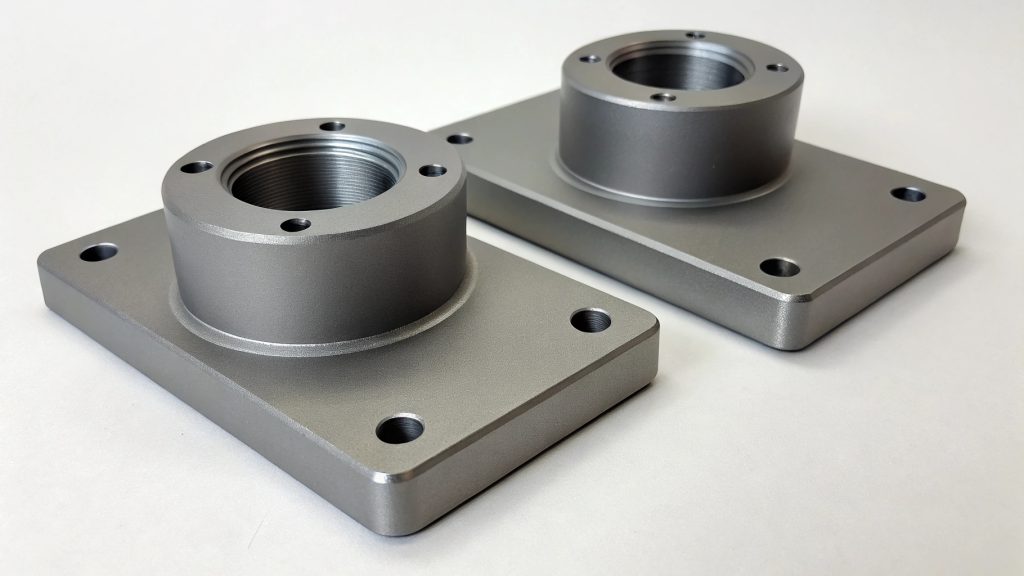
Add an image (SEO requirement)
Place one image near the top of the article.
- Filename: hard-anodize-service-cnc-machined-aluminum-jlypt.jpg
- ALT: hard anodize service on CNC machined aluminum parts—Type III process planning at JLYPT
This satisfies the “image with focus keyword as ALT text” requirement and reinforces topical relevance.
What “hard anodize” actually means in CNC machining terms
In most engineering contexts, “hard anodize” refers to Type III anodizing—an anodic oxide layer grown on aluminum under conditions that promote increased thickness and wear resistance compared to conventional decorative anodizing.
From a CNC machining standpoint, hard anodizing is not a simple coating you “add at the end.” It is a process that interacts with:
- feature geometry (bores, grooves, pockets, sharp corners)
- surface finish (Ra and toolpath witness lines)
- edge preparation (chamfers vs radii vs sharp edges)
- datum strategy (as-machined vs as-finished references)
- masking (threads, bearing seats, sealing lands, electrical contact pads)
A hard anodize service becomes reliable when it’s engineered like any other process step: with defined interfaces, acceptance criteria, and inspection points.
Hard anodize service selection: when Type III is the right tool (and when it’s not)
Hard anodize is commonly selected for wear and durability, but it’s not automatically the best finish for every aluminum component. Before you lock the callout, align the finish to the functional requirement.
Table 1 — When to specify a hard anodize service (Type III) vs alternatives (engineering screening)
| Requirement / constraint | Hard anodize service (Type III) tends to fit | Where you should pause and review | CNC engineering takeaway |
|---|---|---|---|
| Sliding contact / wear faces | Strong candidate | If the mating part is also hard and rough, you may need a friction strategy | Define wear faces explicitly; don’t hard anodize the entire part “by default” |
| Abrasion / handling durability | Strong candidate | Very sharp edges and thin fins can chip | Add controlled edge breaks; avoid knife edges on high-contact areas |
| Tight fits and press fits | Possible with good masking/allowance | Risk of interference after growth | Plan dimensional allowance or mask fits (bores, bearing seats, pilots) |
| Electrical conductivity | Not ideal on contact surfaces | Oxide layer is non-conductive | Mask grounding pads and electrical contact zones |
| Cosmetic “deep black” | Often acceptable | Lot-to-lot variation can occur; rack marks unavoidable | Define cosmetic zoning, viewing conditions, and rack zones |
| Very thin-walled parts | Sometimes risky | Distortion or local variability can be more visible | Review wall thickness, racking plan, and inspection strategy early |
If your primary objective is wear resistance, hard anodize service is usually the first aluminum finish to evaluate—but it still needs the same DFM discipline you apply to tight-tolerance machining.
The quote drivers that control hard anodize service cost, lead time, and yield
A fast quote is easiest when the anodize scope is unambiguous. The most expensive projects are the ones where masking, fit-critical surfaces, or cosmetic expectations weren’t defined until after parts were machined.
Table 2 — Hard anodize service quote drivers (what actually changes the price)
| Quote driver | Why it matters in Type III hard anodize | Common risk if unspecified | What to include in the RFQ |
|---|---|---|---|
| Required surfaces (all-over vs selective) | Selective hard anodize reduces risk on fits but increases masking labor | “Over-finished” fits that lock up | Provide a clear “no anodize” list + masking map |
| Thickness intent | Thickness affects fits, function, and inspection | Parts fail assembly after finish | Specify target/minimum if required; define critical dimensions post-finish |
| Alloy and temper | Different alloys respond differently in appearance and behavior | Mismatched look across assemblies | Lock alloy for cosmetic builds; state exact material callout |
| Surface preparation | As-machined vs blasted vs brushed changes final texture | Cosmetic reject due to toolpath visibility | Specify prep only where needed (A-side), leave non-critical faces flexible |
| Racking / contact points | Rack marks are unavoidable; their location is controllable | Rack mark appears on a customer-visible face | Define rack mark allowed zones |
| Sealing requirement | Sealing affects corrosion behavior and sometimes handling | Disputes about water spots, staining, or corrosion performance | State sealing requirement if your program needs it |
| Inspection & reporting | Thickness measurements and reporting add time | Pass/fail ambiguity at receiving | Define measurement locations and sampling expectations |
| Packaging | Hard anodized parts can still be scratched on cosmetic faces | “Good parts” damaged in transit | Specify protective packaging for A-side faces |
If you want your hard anodize service quote to stay stable from prototype to production, you must define where anodize is allowed, where it’s not, and how you will verify it.
Dimensional planning: how hard anodize affects threads, bores, and fits
Hard anodize changes dimensions. The most practical way to manage this is to treat the anodize layer like a controlled contribution to your tolerance stack.
Even when the oxide layer is thin relative to your overall geometry, it can be decisive on:
- thread pitch diameter
- bearing bores
- dowel holes
- slip fits
- seal lands
Table 3 — Feature-by-feature dimensional risk in hard anodize service
| CNC feature | How hard anodize service can cause failure | Preferred control tactic | What to state on drawing/RFQ |
|---|---|---|---|
| Internal threads | Increased friction, gage failure | Mask threads (preferred) | “MASK all internal threads” and identify features |
| External threads | Nut binds, galling risk changes | Mask or define post-finish gaging | “Threads must gauge after hard anodize” if unmasked |
| Precision bores | Bore ID reduces; fit tightens | Mask bore or set post-finish size requirement | “NO HARD ANODIZE on bore Ø__” (feature ID) |
| Pilot diameters / locating ODs | OD increases; slip fit becomes press | Mask OD or machine allowance | Define “after finish” acceptance if required |
| Dowel holes | Assembly alignment compromised | Mask or ream after finish (program-dependent) | Identify as critical-to-assembly |
| Datum surfaces | Inspection mismatch if datums shift | Decide as-machined vs as-finished datums | “Datums A/B/C are as-machined” if needed |
| Sealing lands | Potential leak / edge chipping | Mask sealing land and define edge break | Call out no-anodize zone boundary from datum |
A hard anodize service becomes predictable when you identify which features must remain “machining-true” and which features can accept growth.
“Buildup” vs “penetration”: why hard anodize must be planned into your machining model
Hard anodize grows from the aluminum surface. For tolerance planning, engineers commonly treat it as a thickness contribution that affects both OD and ID features.
Instead of arguing about terminology, focus on what matters operationally: your drawing must define whether critical dimensions are evaluated pre-finish or post-finish, and which surfaces are masked.
Table 4 — Practical tolerance planning rules for hard anodize service (shop-floor usable)
| Planning question | What to decide | Why it matters |
|---|---|---|
| Are critical fits measured after finish? | Yes / No | Controls whether machining must include finish allowance |
| Are threads allowed to be anodized? | Usually no for tight classes | Prevents gage failures and assembly torque issues |
| Which datums control inspection? | As-machined vs as-finished | Prevents CMM disputes and inconsistent acceptance |
| Will bores be masked? | Often yes on precision bores | Protects bearing fits and alignment |
| Are sliding surfaces the only functional faces? | Sometimes | Selective finishing reduces risk and cost |
| Is cosmetic appearance critical? | If yes, define A-side | Determines surface prep and rack zoning |
If your part is a precision assembly component, assume hard anodize service is part of the tolerance stack until proven otherwise.
Masking strategy: the make-or-break factor in hard anodize service for CNC parts
Masking is where hard anodize service becomes engineering-controlled. It is also one of the biggest cost drivers—so you want to mask only where function demands it, not everywhere.
H2: Hard anodize service masking map checklist
Table 5 — What to mask (and how to communicate it clearly)
| Mask zone | Why it’s masked in hard anodize service | Best way to specify |
|---|---|---|
| Threads (tapped holes) | Protect thread class and gaging | Feature IDs + note: “MASK internal threads” |
| Bearing seats | Maintain precise fit | Detail view with boundaries referenced to datums |
| Press-fit bores | Prevent interference growth | “NO HARD ANODIZE” on bore surface |
| Electrical ground pads | Oxide is non-conductive | Define pad outline with dimensions from datums |
| Seal faces | Avoid leaks and chipping | Specify sealing land as no-anodize + edge break |
| Datum contact pads | Preserve inspection repeatability | Define datum surfaces as as-machined if needed |
| Weld/bond interfaces (if applicable) | Oxide can interfere with joining | Explicit “mask for bonding/welding” surfaces |
Implementation tip: include a one-page masking map as a PDF with shaded areas and short notes. That single page can cut RFQ cycles dramatically.
Surface finish and toolpath decisions that show up after hard anodize
Hard anodize service doesn’t “hide” machining as much as people assume. Depending on surface preparation and the part’s geometry, witness lines, step-over patterns, and tool transitions can become more visible—especially on large flat faces.
Table 6 — CNC machining surface condition vs hard anodize outcome
| Machining condition | What you may see after hard anodize service | Mitigation strategy |
|---|---|---|
| Large step-over on face milling | Visible banding / texture variation | Optimize toolpath, reduce step-over, use finishing pass |
| Inconsistent cutter wear | Patchy reflectivity | Control tool life; standardize finishing tool and parameters |
| Sharp edges left “as-cut” | Edge chipping or bright edge lines | Add consistent chamfer or radius (documented on print) |
| Burrs at cross-holes | Local defects and poor cosmetics | Deburr with consistent method; inspect before finishing |
| Coolant residue in pockets | Staining or surface anomalies | Improve cleaning; design for drainage and access |
| Mixed finishing methods on adjacent faces | Noticeable texture transitions | Define A-side prep requirement; keep B-side flexible |
If you need repeatable appearance, treat surface prep like a controlled operation—just as you control Ra on a sealing land.
Alloy effects: why 6061 and 7075 don’t always “match” under hard anodize service
Different aluminum alloys can respond differently during hard anodizing, particularly in appearance and shade. If you are building a cosmetic assembly with multiple parts, the easiest way to reduce mismatch is to standardize alloy and temper across all visible components.
Table 7 — Alloy planning for hard anodize service (practical guidance)
| Alloy (examples) | What to expect in hard anodize service (high-level) | DFM recommendation for CNC programs |
|---|---|---|
| 6061 | Often used for general CNC parts | Good baseline for repeatability; keep lots consistent |
| 7075 | Common for strength-critical parts | Plan cosmetics carefully; keep visible assemblies consistent |
| Mixed alloys in one assembly | Color/appearance may differ even with identical callout | Avoid mixing on A-side assemblies; if unavoidable, align expectations and approve samples |
If cosmetic matching is a contractual requirement, treat it as an engineering requirement: same alloy, same prep, same rack strategy, and controlled lot processing.
Wear performance: designing sliding interfaces for hard anodize service
Hard anodize is often chosen for sliding contact—but wear performance is still an interface problem. The mating material, surface roughness, lubrication strategy, and contact pressure matter.
Table 8 — Sliding interface design checklist when specifying hard anodize service
| Design factor | Why it matters | Practical CNC + finish action |
|---|---|---|
| Mating material | Hard-on-hard pairing can behave differently than hard-on-soft | Identify mating part; consider inserts or bushings where needed |
| Contact pressure | Higher load increases wear rate | Increase contact area; avoid sharp contact edges |
| Surface roughness | Roughness drives friction and wear | Specify Ra on wear faces; keep toolpath consistent |
| Edge breaks | Edges are high-stress points | Use radii/chamfers at wear boundaries |
| Lubrication | Dry sliding can be harsher | Define lubrication or select a suitable interface design |
| Selective finishing | Only finish wear surfaces if fits are sensitive | Use masking to protect adjacent toleranced features |
A good hard anodize service helps, but it cannot rescue a sliding interface that is under-designed for load and friction.
Sealing, secondary options, and what to clarify (without over-specifying)
Some programs require sealing; others prioritize wear and prefer a specific post-treatment approach. The key is not to over-specify without knowing what your assembly actually needs.
Table 9 — Finish options to clarify in a hard anodize service RFQ
| Option | Why it might be requested | What to clarify in your drawing/RFQ |
|---|---|---|
| Color (black vs natural) | Identification, cosmetics, light control | Define cosmetic faces and acceptance; avoid implying “perfect color match” unless required |
| Sealing requirement | Corrosion behavior and handling | State if sealing is required by your program; otherwise keep it open for DFM discussion |
| Selective vs all-over | Protect fits and datums | Provide masking map and functional priority |
| Surface prep (blast, brush) | Appearance control | Limit prep requirements to A-side surfaces |
If you want both wear resistance and tight dimensional control, selective masking is usually the most effective lever you have.
Defects and troubleshooting: what engineers should recognize early
Hard anodize service has known failure modes. You don’t need to be a chemist to prevent most of them—you need a buildable spec, good drainage and deburring, consistent surface prep, and a realistic cosmetic definition.
Table 10 — Common hard anodize service issues and prevention actions
| Issue | What you see | Likely contributors | Prevention actions (CNC + finishing definition) |
|---|---|---|---|
| Uneven appearance on flats | Patchiness or banding | Toolpath artifacts, inconsistent prep | Define A-side prep; improve finishing pass strategy |
| Edge chipping | Small chips at sharp corners | Insufficient edge break, handling impacts | Add controlled chamfers/radii; specify packaging protection |
| Rack marks on visible faces | Contact points visible | No rack zone defined | Define allowed rack zones on hidden surfaces |
| Fit interference | Assembly won’t slide or press properly | Anodize growth on fits | Mask fits or machine finish allowance with defined post-finish acceptance |
| Thread gage failures | Go gage fails; torque rises | Threads anodized | Mask threads or require functional gaging after finish |
| Staining / handling marks | Spots or discoloration | Poor cleaning, trapped coolant, inadequate packaging | Improve cleaning access; specify packaging for cosmetic faces |
Preventing these issues starts in your CAD/CAM and drawing notes—not at receiving inspection.
Inspection planning: how to make hard anodize service measurable and enforceable
A hard anodize service is easiest to manage when pass/fail criteria are measurable. Inspection typically includes thickness checks at defined locations, plus functional checks on threads and fits.
Table 11 — Inspection plan components for hard anodize service on CNC parts
| Requirement | How it’s typically verified | What you should define |
|---|---|---|
| Thickness | Non-destructive thickness measurement methods (program-dependent) | Measurement locations tied to datums; acceptance range if required |
| Cosmetic acceptance | Visual inspection under defined conditions | A-side/B-side, viewing distance, allowable rack marks |
| Thread functionality | Go/No-Go gages | Whether threads are masked or must gauge after finish |
| Fit functionality | Functional gage or assembly check | Which features are critical-to-assembly and checked post-finish |
| Coverage of required surfaces | Visual verification | Clear definition of “no anodize” zones and boundaries |
| Documentation | CoC and any required reports | Request only what your program needs |
If you don’t define measurement locations and acceptance criteria, you risk inconsistent receiving decisions—especially on complex geometry where thickness can vary by location.
Drawing callouts that shops can build: templates for hard anodize service
The highest-leverage improvement you can make is turning “Hard anodize, black” into a structured note that answers: where, how much, what is masked, and what is functional after finish.
H2: Hard anodize service drawing callout building blocks
Table 12 — Callout elements to include (and why they matter)
| Callout element | What to include | Why it matters for CNC production |
|---|---|---|
| Process | “Type III hard anodize” | Prevents process ambiguity |
| Application area | All-over or selective (with details) | Stops accidental finishing of fits/threads |
| Thickness intent | Target/minimum/range (as program requires) | Drives tolerance planning and inspection |
| Masking | Threads, bores, datums, pads | Protects assembly-critical geometry |
| Cosmetic zoning | A-side/B-side and inspection condition | Reduces subjective rejections |
| Rack mark zones | Allowed contact areas | Makes racking buildable |
| Functional acceptance | Threads gauge / fits assemble after finish | Converts intent into verifiable requirements |
Table 13 — Practical note templates (edit placeholders to match your program)
| Use case | Template note (structure you can paste into a drawing) |
|---|---|
| Wear-focused component with sensitive fits | “HARD ANODIZE SERVICE: Type III hard anodize on surfaces per view. MASK all internal threads and precision bores identified as ‘NO ANODIZE.’ Define rack marks allowed only on designated zone. Critical fits must meet drawing requirements after finish.” |
| Cosmetic + durability housing | “HARD ANODIZE SERVICE: Type III, color black. Surface prep: [as-machined / bead blast] on A-side surfaces only (see view). Rack marks allowed only on hidden surfaces. Mask grounding pads and all threads.” |
| Selective wear pads only | “HARD ANODIZE SERVICE: Type III on wear faces only (see detail). All other surfaces remain as-machined. Mask all datums and fit features as indicated. Inspect thickness at specified locations.” |
These templates avoid overpromising and keep the spec inspectable.
RFQ checklist: the fastest way to get a clean hard anodize service quote
If you want a quote that turns into a stable purchase order, send a finish-ready package instead of a generic “anodize black” note.
H2: Hard anodize service RFQ package (send with every quote request)
Table 14 — RFQ checklist for hard anodize service on CNC machined parts
| RFQ item | What to provide | Why it speeds quoting and reduces risk |
|---|---|---|
| 3D model | STEP preferred | Clarifies geometry, surface area, racking constraints |
| 2D drawing | PDF with GD&T and finish notes | Defines acceptance criteria and critical features |
| Material | Alloy + temper | Helps anticipate appearance and processing behavior |
| Hard anodize definition | Type III hard anodize + any color requirement | Removes ambiguity |
| Thickness intent | Target/minimum/range if required | Enables tolerance planning and inspection |
| Masking map | Highlight no-anodize zones | Protects threads, bores, datums, seal faces |
| Cosmetic zoning | A-side/B-side + viewing condition | Controls rejects and packaging requirements |
| Rack mark zones | Allowed contact surfaces | Makes the part buildable |
| Quantities | Prototype vs production + forecast | Determines racking approach and lot planning |
| Inspection requests | Thickness report, functional checks, cert pack | Aligns cost with real needs |
| Packaging | A-side protection, separators, trays (as needed) | Prevents shipping damage and cosmetic scrap |
Submit anodizing requirements via JLYPT’s anodizing page (internal link):
https://www.jlypt.com/custom-aluminum-anodizing-services/
External standards resources (Dofollow links)
If your internal program references industry standards or you need baseline terminology, these public resources are useful starting points:
- https://www.iso.org/standards.html
- https://www.astm.org/
- https://www.nist.gov/
- https://www.sae.org/standards/
(Your final acceptance must match your drawing notes and any customer/program requirements.)
Three program scenarios (illustrative examples, not claims)
You requested three cases and also required “do not fabricate.” Without customer-approved, publishable project records and permission, it would be inaccurate to present these as verified JLYPT case studies. The scenarios below are common, realistic CNC manufacturing patterns showing how teams typically apply a hard anodize service successfully.
Case Example 1 — Automation wear plate: selective hard anodize service with protected datums
Part profile: CNC-milled aluminum wear plate with datum-controlled mounting pads and a sliding interface
Primary requirement: wear resistance on the sliding face while keeping mounting datums stable
Common failure risks:
- datum pads grow, shifting the assembly stack height
- sliding face performs well but the plate no longer sits flat in the fixture Typical engineering approach:
- apply hard anodize service selectively to the sliding face
- mask datum pads and critical mounting interfaces
- specify edge breaks to reduce chipping at the sliding boundary
- inspect thickness at defined locations on the wear face
Case Example 2 — Precision alignment bracket: hard anodize service with masked dowel holes
Part profile: CNC-milled bracket with tight dowel pin holes and tapped holes for fasteners
Primary requirement: durability and corrosion behavior without losing alignment accuracy
Common failure risks:
- dowel holes shrink and pins no longer seat
- threads become tight and fail gaging Typical engineering approach:
- mask dowel holes (no hard anodize on bore surfaces)
- mask tapped holes, or require post-finish thread gaging if unmasked
- define inspection datums as as-machined to keep CMM correlation consistent
Case Example 3 — Sliding carriage component: hard anodize service focused on wear faces and assembly fits
Part profile: CNC-machined aluminum carriage part with a guided sliding surface and adjacent fit-controlled bores
Primary requirement: stable wear performance under repetitive motion
Common failure risks:
- hard anodize growth tightens nearby bores, causing assembly interference
- rack marks appear on a visible face used as a reference surface Typical engineering approach:
- hard anodize service applied to wear faces only
- masking map protects fit bores and reference pads
- rack mark zones are defined on non-functional edges
- packaging is specified to protect the wear face from handling scratches
Conversion section: how to buy hard anodize service without delays, rework, or “surprise” fit failures
If you’re ordering CNC parts with Type III finishing, the fastest way to prevent schedule slip is a short technical alignment before the first production lot.
What to send to JLYPT for a hard anodize service review
- STEP + PDF drawing (GD&T included)
- Alloy/temper and quantity (prototype vs production)
- Identify fit-critical features: bores, pilots, dowel holes, bearing seats
- Identify threads and whether they must be masked
- Masking map (no-anodize zones)
- A-side/B-side cosmetic definition + allowed rack zones
- Inspection expectations: thickness measurement locations + any functional gaging requirements
Start the anodizing inquiry here (internal link you provided):
https://www.jlypt.com/custom-aluminum-anodizing-services/
Final polish: a one-page checklist engineers can reuse
If you want your hard anodize service to behave like a controlled manufacturing step, check these items before releasing your drawing:
- Define functional surfaces vs cosmetic surfaces (A-side/B-side).
- Decide what must be masked: threads, bores, datums, sealing lands, ground pads.
- Plan dimensions around the finish: are critical sizes verified pre-finish or post-finish?
- Control edge condition: consistent chamfer/radius on contact edges and A-side edges.
- Specify rack zones so unavoidable contact marks are acceptable.
- Define inspection points for thickness and functional gaging.
- Protect the result with packaging requirements for wear faces and cosmetics.
Request a Hard Anodize Service Quote (Type III, Fit-Safe, Production-Ready)
If you need a hard anodize service that preserves threads, protects tight bores, and delivers repeatable wear performance, send your STEP + drawing with a masking map and cosmetic zoning. JLYPT will review your finish intent and quote a production-ready route—without guessing where anodize is allowed.
Submit your anodizing request here:
https://www.jlypt.com/custom-aluminum-anodizing-services/


