
Aluminum Drone Parts Manufacturer: A CNC Machining Playbook for Lightweight Strength, Repeatability, and Scalable Quality
If you’re building UAVs that must fly the same way every time—across batches, across climates, and across payload swaps—your supplier isn’t just a vendor. Your supplier becomes part of the airframe. That’s especially true when most of your structure is aluminum: motor mounts, arm clamps, hubs, gimbal components, housings, rails, brackets, and sealed enclosures.
Selecting an Aluminum drone parts manufacturer is not only about “who can cut metal.” It’s about who can control distortion in thin walls, manage anodize thickness without breaking fits, hold GD&T relationships through fewer setups, and prove it with inspection data that correlates to assembly function.
This article is written for UAV product engineers, manufacturing engineers, and sourcing teams who want a practical, shop-tested guide—heavy on CNC terminology, process realities, and decision-making details.
If you want to discuss a specific UAV part, material, finish, or tolerance stack, JLYPT supports custom CNC drone components here:
https://www.jlypt.com/custom-cnc-uav-parts-manufacturer/
Table of Contents
- Why Aluminum Dominates Modern UAV Hardware
- What “Manufacturer” Should Mean in Aluminum Drone Parts
- Key Aluminum Alloys for Drones (6061-T6 vs 7075-T6 and Beyond)
- CNC Process Map: Milling, Turning, 5-Axis, and Hybrid Routes
- Thin-Wall Aluminum Machining: Distortion, Chatter, and Workholding
- Datums, GD&T, and Why UAV Parts Fail Without Them
- Holes, Bores, Threads: Fits that Survive Vibration and Service
- Surface Finish, Cosmetics, and Functional Surfaces (Ra Targets that Matter)
- Anodize, Hardcoat, and Chemical Conversion: Allowances and Masking
- Heat Management: Aluminum Parts as Heat Sinks and Thermal Structures
- Metrology: CMM, Probing, Gauge Strategy, and What to Put on the Report
- Production Readiness: Fixture Strategy, Traceability, and Change Control
- Cost Drivers (and How to Reduce Cost Without Losing Performance)
- DFM Checklist for UAV Designers (Aluminum-Specific)
- Three CNC Case Studies (Real-World UAV Scenarios)
- RFQ Checklist: What to Send an Aluminum Drone Parts Manufacturer
- How JLYPT Supports Aluminum UAV Parts from Prototype to Batch Production
- Technical Reference Links (Standards & Metrology)
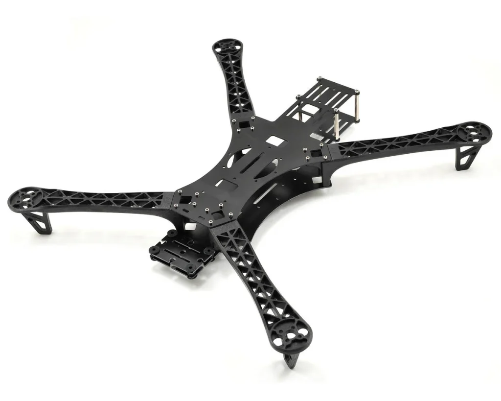
1) Why Aluminum Dominates Modern UAV Hardware
Aluminum remains the default structural material for many drone platforms because it sits at a practical intersection of:
- High specific stiffness (especially 7075-series) for vibration control
- Excellent machinability for complex geometry and tight feature relationships
- Reliable finishing options (anodize, hardcoat, conversion coating)
- Good thermal conductivity (useful for avionics and power electronics)
- Predictable supply chain for prototypes through mid-volume programs
Composite structures can be lighter at the system level, but aluminum still wins when you need precise datums, integrated mounts, threaded durability, heat conduction, and reworkability.
For many programs, the question is not “aluminum or not,” but rather: Which aluminum, which finish, which tolerance scheme, and which manufacturing route keeps performance consistent across builds? That’s the real value an Aluminum drone parts manufacturer should deliver.
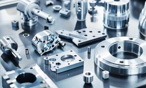
2) What “Manufacturer” Should Mean in Aluminum Drone Parts
Some suppliers can machine aluminum. Fewer can manufacture drone parts.
A true Aluminum drone parts manufacturer should be able to do the following consistently:
- Translate design intent into datum-driven process plans
- Select routes that reduce setup count and cumulative error
- Hold functional GD&T controls (true position, perpendicularity, flatness, profile)
- Control thin-wall distortion with intelligent rough/finish sequencing
- Plan coating allowances (anodize/hardcoat) so that fits still assemble
- Provide metrology outputs that matter: CMM reports, surface finish, critical bores
- Scale from prototype learning to batch repeatability with fixture strategy
Table 1 — Supplier Capability Checklist (What to Verify Early)
| Capability area | What “good” looks like | What you risk without it | What to ask for |
|---|---|---|---|
| CNC capacity | 3-axis + 4th + 5-axis + turning | too many setups, poor feature relationships | machine list + part examples |
| Engineering support | DFM feedback with tolerance logic | expensive drawings, avoidable scrap | DFM notes + proposed datum scheme |
| Finishing knowledge | anodize/hardcoat allowances planned | interference fits, cosmetic rejects | mask plan + thickness expectations |
| Metrology | CMM + probing workflow | “passes calipers” but fails assembly | sample CMM report |
| Repeatability | fixtures and control plans | part-to-part variation across lots | how they lock datum transfer |
| Documentation | FAI / inspection templates | slow ramp-up, confusion | example FAI package |
3) Key Aluminum Alloys for Drones (6061-T6 vs 7075-T6 and Beyond)
Most drone machining RFQs revolve around 6061-T6 and 7075-T6. Both can work—if you choose them for the right reasons and respect how they behave during machining and finishing.
3.1 6061-T6
6061-T6 is a workhorse: stable, corrosion resistant, and generally forgiving. It’s often selected for housings, brackets, covers, and parts that need good cosmetic anodize.
3.2 7075-T6
7075-T6 is chosen for higher strength and stiffness—excellent for structural nodes, motor mounts, and arm interfaces where deflection translates into vibration or control error.
3.3 Other relevant alloys (depending on mission)
- 2024: high strength but less corrosion resistant
- 5083/5052: better for sheet/formed parts than machined precision structures
- 6061-T651 or 7075-T651: stress-relieved plate can improve stability for thin-wall machining
Table 2 — Aluminum Alloy Selection for UAV Parts (Practical Comparison)
| Property / concern | 6061-T6 | 7075-T6 | “Why it matters” in UAVs |
|---|---|---|---|
| Machinability | very good | very good | affects cycle time and surface integrity |
| Strength / stiffness | moderate | high | influences resonance, arm deflection, mount stability |
| Corrosion resistance | better | lower than 6061 | impacts outdoor/sea environments |
| Anodize appearance | typically more uniform | can be less uniform | cosmetic consistency for customer-facing parts |
| Cost | lower | higher | affects total BOM at scale |
| Best use cases | housings, brackets, covers | motor mounts, structural nodes, arm clamps | choose based on load path |
Decision tip: If a part’s function is “locate and align” (motor axis, gimbal axis, payload rail), stiffness often matters more than raw strength. That’s why many UAV structures migrate toward 7075 in alignment-critical regions.
An Aluminum drone parts manufacturer should be comfortable proposing alloy changes when the flight behavior or assembly repeatability demands it.
4) CNC Process Map: Milling, Turning, 5-Axis, and Hybrid Routes
Aluminum is fast to cut, but UAV geometry is rarely simple. Multi-face relationships and thin walls push you toward fewer setups and better datum control.
4.1 3-axis CNC milling
Great for plates, brackets, and parts where most critical features live in one orientation. It can still produce high precision—but only when the setup strategy respects functional datums.
4.2 3+2 (positional) machining
Indexing to multiple sides without continuous simultaneous motion. Often the best value for prismatic multi-face drone parts: lower programming and machine time than full 5-axis, while still reducing setups.
4.3 5-axis CNC machining
5-axis shines for drone nodes and housings where hole patterns, bores, and sealing faces must remain tightly related across multiple faces. Fewer re-clamps generally means fewer opportunities to lose positional truth.
4.4 CNC turning and mill-turn
Anything cylindrical that cares about coaxiality and surface finish—spacers, standoffs, hubs, axles, collars, shafts—often belongs on a lathe or mill-turn, not a mill.
Table 3 — Choosing the Right CNC Route for Aluminum UAV Parts
| Part type | Common UAV examples | Best-fit CNC route | Why it wins |
|---|---|---|---|
| Plates / brackets | sensor mounts, adapter plates | 3-axis milling | fast, economical |
| Structural nodes | arm junctions, motor pods | 3+2 or 5-axis | fewer setups, better feature relationships |
| Cylindrical parts | spacers, hubs, axles | CNC turning / mill-turn | coaxiality + finish control |
| Thin-wall housings | avionics boxes, gimbal shells | 5-axis + HSM strategies | reduced distortion + better access |
| Mixed geometry | bores + flats + holes | mill-turn or 5-axis | eliminates re-chucking error |
A capable Aluminum drone parts manufacturer should be fluent in these routes and explain the trade-offs: setup time, tool reach, inspection approach, and coating implications.
5) Thin-Wall Aluminum Machining: Distortion, Chatter, and Workholding
Many drone parts are stiff on the CAD screen but flexible in real life: thin walls, weight-relief pockets, rib structures, and long arms. Thin-wall aluminum machining is a discipline of managing vibration, residual stress, and clamp pressure.
5.1 Distortion drivers in UAV aluminum parts
- Removing too much material from one side early (unbalanced stress release)
- Clamping that bends the part into the fixture shape
- Heat input from aggressive cutting or poor coolant control
- Tool deflection creating tapered walls and drifting pockets
5.2 Practical methods to control distortion
- Roughing with uniform stock allowance, then semi-finish, then finish
- Symmetric material removal when possible
- Finishing critical datum faces late in the route
- Using soft jaws, vacuum fixtures, or custom nests to support thin regions
- In-process probing to confirm that the part is still sitting where you think it is
Table 4 — Thin-Wall UAV Parts: Failure Modes and Process Fixes
| Symptom | Likely cause | CNC/process fix | Inspection confirmation |
|---|---|---|---|
| lid won’t seal | warped sealing face | finish sealing face last; reduce clamp distortion | flatness check + CMM |
| hole pattern “walks” | re-clamp datum drift | consolidate setups; use datums with hard stops | CMM true position |
| chatter marks | tool reach too long; thin wall resonance | reduce stick-out; adjust toolpath; add support | surface finish measurement |
| bearing bore tight/loose after anodize | no allowance/masking plan | mask or pre-compensate; post-finish size if required | plug gauges + report |
An experienced Aluminum drone parts manufacturer won’t treat thin walls as a nuisance—they’ll treat them as the main engineering challenge and build the plan around them.
6) Datums, GD&T, and Why UAV Parts Fail Without Them
UAV assemblies are alignment systems: motor axes, prop planes, gimbal axes, sensor orthogonality, rail straightness. Traditional ± tolerances can’t fully describe these relationships. GD&T and coherent datums can.
6.1 Datum strategy that matches how the drone assembles
- Datum A: primary seating surface (mounting face)
- Datum B: secondary locating feature (precision edge, slot, bore)
- Datum C: tertiary feature (hole/pin/face) that locks rotation
If a drawing doesn’t define this, the shop will improvise. Different shops (or different shifts) can “hit dimensions” and still produce parts that don’t assemble consistently.
6.2 GD&T controls that often matter in aluminum drone components
- True position for bolt circles and locating holes
- Perpendicularity between seating faces and alignment features
- Flatness on mounting/sealing faces
- Profile for complex sealing grooves or aerodynamic surfaces
Table 5 — GD&T Controls Common in Aluminum UAV Parts
| Functional requirement | Recommended GD&T | Why it matters | Typical metrology |
|---|---|---|---|
| stable motor seating | flatness on mounting face | clamp load consistency; vibration | CMM or granite + indicator |
| consistent bolt circle | true position to A | B | C |
| orthogonal sensor mount | perpendicularity | calibration stability | CMM or height gauge |
| sealing reliability | profile / flatness | leak prevention | CMM + surface finish |
| gimbal smoothness | position/coaxiality on bores | low runout; low friction | CMM + bore gauges |
A serious Aluminum drone parts manufacturer will encourage you to control relationships, not just sizes—and will quote accordingly (often cheaper than blanket-tightening every dimension).
7) Holes, Bores, Threads: Fits that Survive Vibration and Service
Drones live in vibration. If your hole quality, thread strategy, and insert selection are weak, the airframe becomes a maintenance schedule.
7.1 Drilled holes vs reamed holes vs bored holes
- Drilling: fast, but location and roundness can vary
- Reaming: good for precision dowel holes if pre-hole is correct
- Boring: best for critical bearing and pilot bores where geometry is sensitive
7.2 Threads in aluminum: reliability strategies
- Thread milling can produce stronger, cleaner threads than forming taps in many geometries
- Helical inserts are often worth it for high-cycle service points (arms, motor mounts, payload rails)
- Consider thread engagement length, edge distance, and anodize impact
Table 6 — Fit Guide for Aluminum Drone Parts (Common Applications)
| Feature | Typical intent | Preferred process | Notes |
|---|---|---|---|
| motor pilot bore | concentric location | CNC bore + finish pass | control runout via datums |
| dowel pin holes | repeatable assembly | drill undersize + ream | specify pin class if needed |
| bearing seats | controlled press/slip fit | boring; sometimes post-finish sizing | anodize often masked here |
| threaded joints (service) | repeated assembly/disassembly | thread mill + insert | improves field reliability |
| counterbores/spotfaces | stable clamp load | finish pass + deburr | burrs cause false torque |
An Aluminum drone parts manufacturer should be comfortable recommending which features deserve reaming/boring, and which are fine drilled—because not every hole needs to be “perfect,” just the functional ones.
8) Surface Finish, Cosmetics, and Functional Surfaces
UAV parts often combine three surface requirements in one part:
- cosmetic (visible housings, brand-facing panels)
- functional (sealing lands, bearing seats)
- structural (interfaces where friction and clamp load matter)
8.1 Surface roughness targets that commonly matter
- Bearing seats: smoother Ra helps consistent friction behavior
- Sealing lands: smooth enough for consistent sealing; too smooth can also be problematic depending on elastomer behavior
- Cosmetic surfaces: bead blast patterns must be controlled to avoid patchiness after anodize
Table 7 — Surface Finish Targets (Typical Guidance, Part-Dependent)
| Surface type | What matters | Typical machining approach | Verification |
|---|---|---|---|
| bearing seat | low Ra + good form | boring + finish pass | Ra tester + bore gauge |
| sealing land | stable Ra + flatness | face milling + light finish | Ra tester + flatness |
| clamp interfaces | avoid burrs; consistent texture | spotface finish + deburr | visual + indicator |
| cosmetic exterior | uniform appearance after anodize | controlled bead blast + consistent toolpath | visual standard sample |
A credible Aluminum drone parts manufacturer will ask which surfaces are “Class A cosmetic,” because applying cosmetic standards everywhere can inflate cost with no flight benefit.
9) Anodize, Hardcoat, and Chemical Conversion: Allowances and Masking
Finishing is not an afterthought in aluminum drone components. It changes dimensions, friction, electrical contact, and assembly feel.
9.1 Anodize / hardcoat basics (in manufacturing terms)
- Coatings add thickness; some grows outward, some penetrates the surface
- Hardcoat typically increases wear resistance but complicates close fits
- Cosmetic anodize can vary by alloy and batch; consistency needs process control
9.2 Common UAV finishing choices
- Type II anodize for corrosion + cosmetics
- Type III hardcoat for wear surfaces (rails, sliding interfaces, arm clamps)
- Chemical conversion coating when you need conductivity or paint adhesion
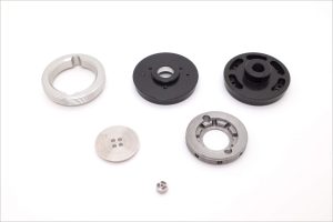
Table 8 — Finish Planning for CNC Aluminum Drone Parts
| Finish | Typical UAV reason | Fit impact | Best practice |
|---|---|---|---|
| anodize (Type II) | corrosion + appearance | moderate | specify color/finish class; define cosmetic zones |
| hardcoat (Type III) | wear resistance | higher | mask precision bores; plan allowance |
| conversion coating | conductivity + corrosion | low | use where grounding matters |
| bead blast + anodize | uniform cosmetics | indirect | lock blast media + pressure + time |
Table 9 — Where Masking is Commonly Worth It
| Feature | Why mask | What happens if you don’t |
|---|---|---|
| bearing seats | protect fit + form | binding or loose bearing feel |
| datum faces | preserve precise seating | assembly drift, torque variation |
| grounding pads | maintain conductivity | intermittent electrical contact |
| sliding rails | control friction | stick-slip or accelerated wear |
An Aluminum drone parts manufacturer should talk about finish early—before the first chips are made—because coating decisions can dictate the machining strategy (especially for final sizing).
10) Heat Management: Aluminum Parts as Heat Sinks and Thermal Structures
Aluminum isn’t only structural in drones. It’s often your thermal management strategy: motor heat paths, ESC heat sinking, camera module heat spreaders, and sealed avionics boxes that must dump heat to airflow.
Key manufacturing considerations:
- Flatness and contact area on thermal interfaces
- Surface finish and coatings affecting thermal contact resistance
- Fastener strategy for consistent pressure distribution
Table 10 — Thermal Interface Features (Machining + Inspection Notes)
| Feature | Why it matters | Machining approach | Inspection |
|---|---|---|---|
| heat spreader face | contact uniformity | face mill + finish pass | flatness + Ra |
| threaded standoffs | clamp load | controlled spotface | depth + burr check |
| finned heat sink geometry | airflow and surface area | HSM toolpaths | dimensional sampling |
| enclosure-to-frame interface | heat path + sealing | finish late; control datums | CMM + flatness |
A strong Aluminum drone parts manufacturer can treat thermal features as functional geometry, not cosmetic machining.
11) Metrology: CMM, Probing, Gauge Strategy, and Reporting
Inspection must match function. Many UAV failures come from parts that “measure fine” but don’t assemble predictably because relationships weren’t verified.
11.1 In-process probing
Probing on the machine can:
- verify datum pickup
- reduce scrap by catching tool wear drift
- support closed-loop offset corrections on critical features
11.2 CMM inspection
CMM reporting is especially valuable for:
- true position of hole patterns
- perpendicularity/parallelism between functional faces
- profile tolerances on grooves and complex surfaces
Table 11 — Inspection Deliverables That Help UAV Programs
| Deliverable | Best time to require it | What it prevents |
|---|---|---|
| First Article Inspection (FAI) | first build / rev change | surprises during assembly |
| CMM report (critical GD&T) | alignment-critical parts | vibration and pointing drift |
| surface roughness report | bearing seats, seals | stick-slip, leakage |
| material cert (as needed) | controlled programs | traceability issues |
| SPC sampling plan | pilot/batch production | lot-to-lot drift |
For general references on metrology and dimensional control (useful when writing internal specs), you can consult:
- https://www.iso.org/standards.html
- https://www.asme.org/codes-standards
- https://www.nist.gov/
- https://www.astm.org/standards
12) Production Readiness: Fixtures, Repeatability, and Change Control
“Prototype quality” and “production-ready quality” are not the same. In drones, your biggest risk at ramp is not that parts are out of spec—it’s that variation increases when you scale quantities.
A production-minded Aluminum drone parts manufacturer typically invests in:
- dedicated soft jaws or modular fixtures
- stable datum transfer methods across operations
- tool life management and offset discipline
- documented revision control and inspection templates
Table 12 — Prototype vs Batch: What Changes in the Shop
| Category | Prototype approach | Batch-ready approach | Why it matters |
|---|---|---|---|
| fixturing | quick vise + parallels | dedicated nests/soft jaws | repeatability and speed |
| inspection | spot checks | defined critical feature list + CMM | consistent assembly outcomes |
| programming | “works once” toolpath | optimized, stable toolpaths | cycle time + tool life |
| finishing | “best effort” cosmetics | controlled blast/anodize flow | consistent appearance |
13) Cost Drivers (and How to Reduce Cost Without Losing Performance)
Cost optimization is not the enemy of precision. The enemy is unclear function.
13.1 Major cost drivers in CNC aluminum drone parts
- Too many tight tolerances on non-functional features
- High setup count due to poor datum planning
- Deep pockets and long-reach tooling driving chatter and slow feeds
- Cosmetic requirements specified everywhere
- Post-anodize rework due to missing allowance strategy
Table 13 — Cost Drivers and Safe Optimization Moves
| Cost driver | Why it raises price | Safer optimization |
|---|---|---|
| blanket ±0.01 mm everywhere | slows machining + increases inspection | tighten only datums and functional interfaces |
| too many setups | labor + error | redesign to allow 3+2/5-axis completion |
| thin ribs + deep pockets | chatter + scrap | increase wall thickness or add ribs strategically |
| unbounded cosmetics | finishing rejections | define “Class A” surfaces only |
| no coating plan | rework | mask or allow for coating growth early |
A good Aluminum drone parts manufacturer will ask questions that feel “annoying” but save money: which faces are functional, where does it seal, what aligns to what, what is the assembly sequence?
14) DFM Checklist for UAV Designers (Aluminum-Specific)
Design for machining is not about dumbing down your part. It’s about making sure the geometry you need can be produced reliably and measured.
Table 14 — DFM for CNC Aluminum Drone Components
| Design element | Best practice | Why it helps | Common mistake |
|---|---|---|---|
| internal corners | use generous radii | stronger tools, less deflection | tiny radii force small cutters |
| wall thickness | keep thin walls supported | reduces distortion | “thin everywhere” weight reduction |
| datum features | define real assembly references | stable setups and CMM | datums on non-functional faces |
| hole patterns | use true position | preserves alignment intent | relying on ± location dims |
| coating | define masked areas | protects fits and grounding | ignoring anodize growth |
| threads | plan inserts for service points | durability | stripping aluminum threads |
15) Three CNC Case Studies (Real-World UAV Scenarios)
The following cases illustrate typical decision points when working with an Aluminum drone parts manufacturer—where CNC process planning, GD&T, and finishing strategy directly change flight behavior and assembly consistency.
Case Study 1 — 7075 Motor Mount Ring: Vibration Reduction Through True Position Control
Part: Motor mount ring, 7075-T6, anodized.
Problem: Two “identical” airframes showed different vibration signatures at specific RPM bands. Motors and props were swapped; the behavior followed the mount ring.
Root cause: Hole pattern location varied in a way that caliper checks didn’t catch; the drawing controlled hole size but under-defined the functional relationship between the bolt circle and the seating datum.
Manufacturing fix:
- Established a clear datum scheme tied to the seating face and pilot bore.
- Applied GD&T true position for bolt-circle holes relative to the functional datums.
- Consolidated machining to reduce re-clamping error; finished the seating face in the last operation.
- Verified via CMM report focusing on true position and perpendicularity.
Result: Assembly became repeatable; motor alignment stabilized; vibration variation across builds dropped without tightening non-critical dimensions.
Case Study 2 — Thin-Wall Avionics Housing: Distortion Control with Rough/Finish Sequencing
Part: Lightweight avionics housing, 6061-T6, bead blast + anodize.
Problem: Lid fit and screw alignment drifted after machining; some units required force to close or showed inconsistent gasket compression.
Root cause: Unbalanced roughing released stress and warped the sealing flange. Clamp pressure during machining also contributed.
Manufacturing fix:
- Adopted a staged approach: rough leaving uniform stock, then semi-finish, then finish sealing surfaces last.
- Used supportive fixturing (custom nest/soft jaws) to reduce clamp-induced bending.
- Added inspection points on sealing face flatness and hole pattern true position.
Result: Lids assembled consistently, sealing load was uniform, and cosmetic anodize improved because the surface prep became more consistent.
Case Study 3 — Gimbal Bracket and Bearing Seat: Eliminating “Notchy” Rotation After Hardcoat
Part: Gimbal bracket with bearing bores, aluminum with hardcoat.
Problem: Smooth rotation before coating; slight notchiness after hardcoat, inconsistent bearing installation force.
Root cause: Hardcoat thickness affected critical bores; the process lacked a dedicated plan for functional surfaces that should not build thickness.
Manufacturing fix:
- Masked bearing seats (or controlled pre-coat sizing with post-finish sizing when masking wasn’t feasible).
- Improved bore strategy using boring cycles and controlled finish passes for better form.
- Verified bore size and relationship using CMM and bore gauges; set acceptance criteria for bearing press force.
Result: Rotation consistency returned, bearing installation became predictable, and the gimbal performance became stable across batches.
16) RFQ Checklist: What to Send an Aluminum Drone Parts Manufacturer
If you want fast quoting and fewer revisions, send an RFQ package that makes functional requirements obvious.
Table 15 — RFQ Package Checklist (Best Practice)
| Item | What to provide | Why it matters |
|---|---|---|
| CAD | STEP + native file (if possible) | reduces interpretation risk |
| Drawing | PDF with datums + GD&T | defines functional relationships |
| Material | alloy + temper (e.g., 7075-T6) | affects stability + finish |
| Finish | anodize/hardcoat/conversion + color | affects fits and cosmetics |
| Quantity | prototype qty + likely next lot | drives fixture and inspection planning |
| Critical features | top 5 functional features | focuses inspection budget |
| Inspection | FAI/CMM/surface finish requirements | avoids mismatched expectations |
| Assembly notes | mating parts + fasteners | helps define datums and fits |
17) How JLYPT Supports Aluminum UAV Parts (Prototype to Batch)
If you’re looking for an Aluminum drone parts manufacturer that can support both engineering agility and manufacturing discipline, JLYPT focuses on CNC process planning that respects UAV realities: alignment, vibration, sealing, repeatable assembly, and finish-controlled fits.
Explore custom CNC UAV parts support here:
https://www.jlypt.com/custom-cnc-uav-parts-manufacturer/
You can also start from the main site for broader CNC machining capabilities:
https://www.jlypt.com/
Typical parts supported in aluminum UAV programs:
- motor mounts, hubs, clamps, arm interfaces
- gimbal brackets and housings
- avionics enclosures and lids
- sensor mounts, payload rails, adapters
- standoffs, spacers, collars, turned components
18) Technical Reference Links (Standards & Metrology)
(Useful when building internal specifications, inspection templates, or supplier quality requirements.)


