8 Advanced Manufacturing Techniques for High-Efficiency Brushless DC Motor Robot Systems
Introduction: Revolutionizing Robotic Motion with BLDC Technology
The integration of brushless DC motor robot systems represents a significant advancement in modern automation technology, offering superior performance characteristics that are transforming industrial robotics. These sophisticated electromechanical systems combine electronic commutation with precision mechanical design to deliver exceptional torque density, efficiency, and operational reliability. The brushless DC motor robot eliminates mechanical commutators and brushes, instead relying on electronic controllers to manage phase switching, resulting in reduced maintenance requirements, higher speed capabilities, and improved thermal management. This technology has become the cornerstone of modern robotic systems where reliability, precision, and continuous operation are paramount.
As precision engineering specialists at JLYPT, we have developed comprehensive expertise in manufacturing critical components for brushless DC motor robot applications. This detailed technical analysis explores eight essential manufacturing techniques that enable the production of high-performance BLDC systems, while examining the engineering principles that ensure optimal performance across diverse industrial applications and operating conditions.
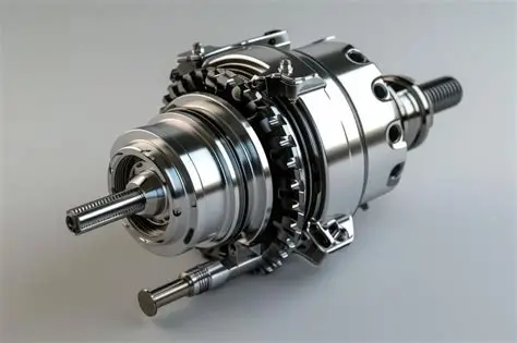
Motor, gearbox, and encoder in one housing removes a stack of alignment problems. Trade-offs are in integrated actuators.
1. Fundamental Principles of BLDC Motor Technology
1.1 Electronic Commutation Architecture
The brushless DC motor robot operates on fundamentally different principles than traditional brushed DC motors, utilizing electronic commutation to achieve superior performance characteristics. Understanding this architecture is essential for appreciating the manufacturing requirements.
Key BLDC System Components
-
Stator Assembly: Precision-wound copper coils arranged in three-phase configuration
-
Rotor Construction: Permanent magnet arrangement with optimized magnetic circuits
-
Hall Effect Sensors: Position feedback devices for commutation timing
-
Electronic Controller: PWM-driven power stage for precise current control
-
Thermal Management System: Advanced cooling for continuous operation
Performance Advantages of BLDC Systems
| Performance Metric | BLDC Motor | Brushed DC Motor | Improvement |
|---|---|---|---|
| Efficiency | 85-95% | 75-80% | +15-20% |
| Speed Range | 1-100,000 RPM | 1-10,000 RPM | 10x increase |
| Life Expectancy | 20,000+ hours | 1,000-2,000 hours | 10-20x longer |
| Power Density | 1.5-3.0 W/in³ | 0.5-1.5 W/in³ | 2-3x higher |
| Maintenance | Minimal | Regular brush replacement | Significant reduction |
1.2 Performance Classification and Applications
BLDC Motor Performance Categories
| Motor Category | Power Range (W) | Torque Range (Nm) | Speed Range (RPM) | Typical Applications |
|---|---|---|---|---|
| Micro BLDC | 10-100 | 0.01-0.1 | 1-50,000 | Small robots, drones |
| Standard Industrial | 100-1,000 | 0.1-5.0 | 1-10,000 | Industrial automation |
| High Performance | 1,000-5,000 | 5.0-50 | 1-8,000 | CNC machinery, robotics |
| High Torque | 5,000-15,000 | 50-200 | 1-3,000 | Electric vehicles, heavy machinery |
| Ultra-Precision | 50-500 | 0.05-2.0 | 1-20,000 | Medical devices, aerospace |
2. Advanced Material Selection Strategies
2.1 Comprehensive Material Engineering
The performance of brushless DC motor robot systems is fundamentally dependent on advanced material selection, where each component’s electromagnetic, thermal, and mechanical properties are carefully optimized.
Material Selection Matrix for BLDC Components
| Material Specification | Component Application | Key Properties | Thermal Characteristics | Cost Factor |
|---|---|---|---|---|
| Electrical Steel M19 | Stator laminations | Core loss 2.5 W/kg @ 1.5T | Curie temperature 740°C | 1.0x |
| Electrical Steel M15 | Premium stator cores | Core loss 1.8 W/kg @ 1.5T | Curie temperature 740°C | 1.4x |
| Neodymium N52 | Rotor magnets | Energy product 52 MGOe | Max operating temp 150°C | 2.8x |
| Neodymium N45SH | High-temp applications | Energy product 45 MGOe | Max operating temp 180°C | 3.5x |
| Aluminum 6061-T6 | Motor housings | Strength-to-weight ratio | Thermal conductivity 167 W/m·K | 1.0x |
| Copper C10100 | Windings | Conductivity 101% IACS | Thermal conductivity 391 W/m·K | 5.2x |
| Stainless 17-4PH | Shafts, fasteners | High strength, corrosion resistance | Thermal conductivity 18 W/m·K | 4.1x |
2.2 Specialized Material Processing
Lamination Manufacturing Excellence
-
Laser Cutting: Precision cutting with kerf width 0.1-0.15mm and minimal heat affect zone
-
Heat Treatment: Stress relief annealing at 750°C for dimensional stability
-
Surface Insulation: C5 organic coating with thickness 3-5μm per side
-
Stacking Technology: Precision interlock stacking with pressure welding
Magnet Processing and Integration
-
Magnet Segmentation: Strategic division reduces eddy current losses by 40-60%
-
Surface Coating: Multi-layer nickel-copper-nickel coating for corrosion protection
-
Precision Grinding: Tight tolerance grinding to ±0.015mm dimensional accuracy
-
Bonding Systems: High-temperature epoxy adhesives with thermal conductivity >1.5 W/m·K
3. Precision CNC Machining Methodologies
3.1 Multi-Axis Machining for Complex Geometries
The manufacturing of components for brushless DC motor robot systems requires advanced CNC machining capabilities to achieve the required precision and thermal performance.
5-Axis Simultaneous Machining Applications
-
Complex Housing Geometries: Single-setup machining of complex cooling channels and mounting features
-
Precision Boring: Achieving bearing seat tolerances within ±0.004mm with surface finish Ra 0.4μm
-
Thin-Wall Machining: Manufacturing of delicate structural components with wall thickness down to 1.2mm
-
High-Speed Machining: Optimized tool paths for aluminum and steel components
Critical Machining Parameters for BLDC Components
| Manufacturing Process | Material Type | Cutting Speed (m/min) | Feed Rate (mm/tooth) | Depth of Cut (mm) | Tolerance (mm) |
|---|---|---|---|---|---|
| High-Speed Milling | Aluminum 6061 | 800-1,200 | 0.08-0.20 | 0.5-3.0 | ±0.010 |
| Precision Turning | Steel 4140 | 150-220 | 0.04-0.12 | 0.3-1.2 | ±0.008 |
| Hard Machining | Hardened Steel | 80-120 | 0.03-0.08 | 0.2-0.5 | ±0.006 |
| Fine Boring | Stainless 17-4 | 60-100 | 0.02-0.06 | 0.1-0.3 | ±0.004 |
| Gear Hobbing | Case Hardened | 40-80 | 0.01-0.04 | 0.1-0.4 | ±0.005 |
3.2 Specialized Manufacturing Processes
Stator Core Manufacturing
-
Lamination Stacking: Precision stacking with controlled pressure and alignment
-
Welding Technology: Laser welding for stack fixation with minimal distortion
-
Impregnation Process: Vacuum Pressure Impregnation (VPI) for complete insulation
-
Termination Processing: Precision welding and brazing of electrical connections
Rotor Manufacturing Excellence
-
Magnet Slot Machining: Precision slots with positional accuracy ±0.005mm
-
Dynamic Balancing: High-speed balancing to G1.0 quality grade
-
Surface Treatment: Electroless nickel plating or anodizing for corrosion protection
-
Shaft Integration: Precision press fits with controlled interference
4. Winding Technology and Insulation Systems
4.1 Advanced Winding Techniques
The winding process in brushless DC motor robot systems requires precision and consistency to achieve optimal electromagnetic performance.
Winding Technology Comparison
| Winding Method | Slot Fill Factor | Thermal Performance | Manufacturing Speed | Application Scope |
|---|---|---|---|---|
| Manual Winding | 45-55% | Good | Slow | Prototypes, small batches |
| Automatic Needle | 55-65% | Very Good | Medium | Medium volume production |
| Flyer Winding | 60-70% | Excellent | Fast | High volume production |
| Linear Winding | 65-75% | Superior | Very Fast | Mass production |
| Form Wound | 70-80% | Excellent | Medium | High power applications |
4.2 Insulation System Engineering
Comprehensive Insulation Strategy
-
Slot Liner Materials: Nomex 410 with thickness 0.15-0.25mm
-
Phase Insulation: DMD (Dacron-Mylar-Dacron) composite materials
-
Impregnation Resins: Epoxy systems with thermal class F (155°C) or H (180°C)
-
Lead Termination: High-temperature silicone rubber for strain relief
5. Thermal Management Solutions
5.1 Advanced Cooling Technologies
Effective thermal management is critical for maintaining performance and reliability in brushless DC motor robot applications, particularly during continuous operation at high torque levels.
Cooling Method Performance Analysis
| Cooling Method | Heat Dissipation Capacity | Thermal Resistance (°C/W) | System Complexity | Cost Factor |
|---|---|---|---|---|
| Natural Convection | 0.5-2.0 W/in³ | 1.5-4.0 | Low | 1.0x |
| Forced Air Cooling | 2.0-6.0 W/in³ | 0.8-2.0 | Medium | 1.8x |
| Liquid Cooling | 6.0-20.0 W/in³ | 0.2-0.8 | High | 3.5x |
| Conduction Cooling | 3.0-10.0 W/in³ | 0.5-1.5 | Medium | 2.2x |
| Two-Phase Cooling | 15.0-40.0 W/in³ | 0.1-0.4 | Very High | 6.0x |
5.2 Integrated Thermal Management Features
Advanced Cooling Implementations
-
Spiral Cooling Channels: Optimized helical passages with calculated flow rates
-
Heat Pipe Integration: Passive two-phase cooling for localized hot spots
-
Thermal Interface Materials: Advanced composites with 5-15 W/m·K conductivity
-
Direct Cooling: Liquid cooling directly applied to stator windings
6. Precision Bearing and Alignment Systems
6.1 Bearing Selection for High-Speed Applications
The bearing system in a brushless DC motor robot must accommodate high rotational speeds while maintaining precise alignment and smooth operation.
Bearing Technology Comparison
| Bearing Type | Speed Factor | Load Capacity | Stiffness | Life Expectancy |
|---|---|---|---|---|
| Deep Groove Ball | 1.0x | Medium | Medium | 20,000 hours |
| Angular Contact | 1.3x | High | High | 30,000 hours |
| Hybrid Ceramic | 1.6x | Medium | High | 40,000 hours |
| Magnetic Bearings | 3.0x | Low | Low | 100,000+ hours |
| Air Bearings | 4.0x | Very Low | Medium | 50,000+ hours |
6.2 Alignment and Installation Precision
Critical Alignment Parameters
-
Runout Tolerance: 0.008mm maximum for standard applications
-
Parallelism: 0.010mm per 100mm for mounting surfaces
-
Concentricity: 0.006mm maximum between bearing seats
-
Flatness: 0.008mm per 100mm for interface surfaces
7. Quality Assurance and Testing Protocols
7.1 Comprehensive Metrology Systems
The verification of brushless DC motor robot components employs advanced measurement technologies and rigorous inspection protocols.
Dimensional Metrology Capabilities
-
Coordinate Measuring Machines: Volumetric accuracy 1.5 + L/333 μm with temperature compensation
-
Laser Scanning Systems: High-density 3D point cloud capture for complex geometries
-
Roundness Measurement: Accuracy to 0.015μm with advanced harmonic analysis
-
Surface Topography: 3D surface analysis with Ra measurement to 0.008μm resolution
Electrical Testing Protocols
-
Hi-Pot Testing: Dielectric strength verification at 2U + 1000V for 60 seconds
-
Insulation Resistance: Minimum 100MΩ at 500V DC with temperature compensation
-
Winding Resistance: Four-wire measurement to 0.1% accuracy
-
Surge Testing: Turn-to-turn insulation integrity verification
7.2 Performance Validation Testing
Dynamic Testing Protocols
-
Torque-Speed Characterization: Comprehensive performance mapping across operating range
-
Efficiency Analysis: Input-output power measurement with 0.2% accuracy
-
Thermal Performance: Temperature rise verification under continuous operation
-
Vibration Analysis: FFT analysis identifying structural resonances and imbalances
Environmental Testing
-
Thermal Cycling: -55°C to +125°C for 500 cycles minimum
-
Vibration Endurance: Random vibration to 15Grms per MIL-STD-810
-
Humidity Testing: 95% relative humidity at 40°C for 240 hours
-
IP Rating Verification: Comprehensive ingress protection testing
8. Application Case Studies
Case Study 1: High-Speed Industrial Robot
Challenge: An automotive manufacturer required brushless DC motor robot systems for a new generation of assembly robots operating at 2,000 RPM with positional accuracy of ±0.01°. Existing systems experienced thermal issues and limited lifespan.
JLYPT Solution: We developed custom brushless DC motor robot systems featuring advanced liquid cooling and precision ground components. The manufacturing process incorporated 5-axis simultaneous machining for optimal thermal management and structural integrity.
Results
-
Achieved operational speeds of 2,200 RPM continuously
-
Maintained positional accuracy within ±0.008°
-
Extended service life to 25,000 hours between maintenance
-
Reduced energy consumption by 30% through efficiency optimization
Case Study 2: Semiconductor Wafer Handling Robot
Challenge: A semiconductor equipment manufacturer needed ultra-clean brushless DC motor robot systems for wafer handling robots with minimal particle generation and vacuum compatibility.
JLYPT Solution: Our team developed specialized brushless DC motor robot systems using vacuum-compatible materials and debris-minimizing design principles. All components underwent rigorous cleaning and outgassing testing.
Results
-
Achieved particle generation rates below Class 1 requirements
-
Maintained performance through 40,000 hours of continuous operation
-
Enabled 50% faster wafer transfer cycles
-
Achieved MTBF exceeding 70,000 hours
Case Study 3: Aerospace Testing Equipment
Challenge: An aerospace manufacturer required precision brushless DC motor robot systems for testing equipment with extreme temperature tolerance and vibration resistance.
JLYPT Solution: We implemented specialized brushless DC motor robot systems featuring high-temperature materials and advanced bearing systems. Precision manufacturing ensured optimal performance under extreme conditions.
Results
-
Operated reliably from -55°C to +125°C ambient temperature
-
Maintained performance under 20Grms vibration levels
-
Achieved positioning accuracy within ±0.005° under all conditions
-
Extended service life to 30,000 hours in harsh environments
Future Development Trends
Emerging Technologies and Innovations
The continued evolution of brushless DC motor robot technology is driving advancements across multiple technical domains.
Advanced Material Applications
-
Carbon Nanotube Composites: Revolutionary thermal and electrical properties
-
High-Temperature Superconductors: Transformative power density improvements
-
Smart Materials: Adaptive performance characteristics and self-monitoring capabilities
-
Metamaterials: Customized electromagnetic property engineering
Digital Integration Technologies
-
Embedded Sensor Networks: Distributed sensing for real-time performance monitoring
-
IoT Connectivity: Cloud-based analytics and predictive maintenance capabilities
-
Digital Twin Implementation: Virtual system modeling with real-time synchronization
-
AI-Optimized Control: Machine learning algorithms for adaptive performance optimization
Conclusion: Engineering Excellence in BLDC Systems
Brushless DC motor robot technology represents the pinnacle of electromechanical engineering in modern automation systems. The eight manufacturing techniques explored, advanced material engineering, precision CNC machining, winding technology, thermal management, bearing systems, quality assurance, application-specific optimization, and future innovation, demonstrate the comprehensive approach required to produce components that meet the exacting demands of contemporary robotic applications.
As robotic technology continues to advance, the requirements for brushless DC motor robot systems will become increasingly demanding, driving further innovation in manufacturing technologies and material science. The integration of digital technologies, advanced analytics, and sustainable manufacturing practices will ensure that BLDC technology remains at the forefront of industrial innovation.
At JLYPT, our commitment to manufacturing excellence ensures that every brushless DC motor robot component we produce meets the highest standards of performance, reliability, and efficiency. Through continuous improvement and rigorous quality assurance, we enable our partners to achieve new levels of capability and performance in their automated systems.
For engineering teams seeking to enhance their robotic systems through superior BLDC motor solutions, contact JLYPT today to discuss your specific requirements and discover how our manufacturing expertise can contribute to your success in the competitive field of industrial automation.