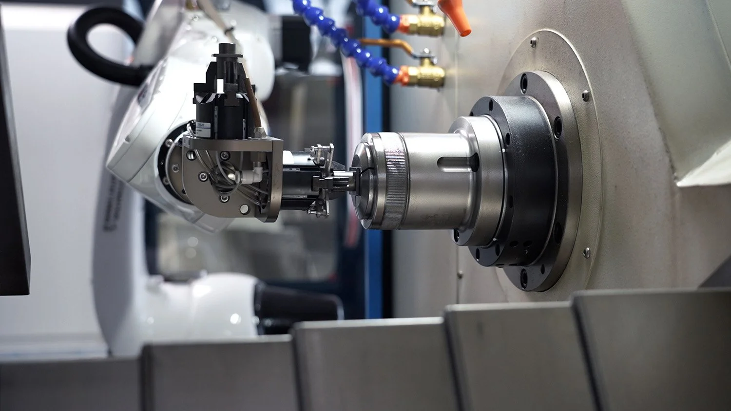
The Complete Guide to CNC Milled Carbon Fiber Parts: Precision Manufacturing for High-Performance Applications
Introduction: The Evolution of Carbon Fiber in Precision CNC Machining
Carbon fiber has emerged as a transformative material in advanced manufacturing, offering an exceptional strength-to-weight ratio that traditional metals cannot match. CNC milled carbon fiber parts represent the intersection of advanced material science and precision manufacturing, enabling breakthroughs across aerospace, automotive, medical, and high-tech industries. The machining process for carbon fiber composites requires specialized expertise, as the material’s anisotropic nature and abrasiveness present unique challenges that demand sophisticated tooling strategies and precise parameter control.
The global market for custom carbon fiber parts continues to expand rapidly, driven by increasing demand for lightweighting solutions across industries . As a CNC machining service provider with extensive experience in advanced composites, we’ve developed proprietary techniques for optimizing the manufacturing process for carbon fiber components. This comprehensive guide explores the technical considerations, machining methodologies, and practical applications of CNC milled carbon fiber parts, providing valuable insights for engineers and designers seeking to leverage this exceptional material.
Understanding Carbon Fiber Materials: Composition and Properties
Carbon Fiber Characteristics and Classification
Carbon fiber consists of thin, strong crystalline filaments of carbon that are twisted together to form a yarn, which can be woven into fabrics or used in non-woven forms. The material is typically combined with polymer resins to create carbon fiber reinforced polymer (CFRP) composites, which offer exceptional mechanical properties:
Table 1: Comparison of Carbon Fiber Types and Properties
| Carbon Fiber Type | Filament Count | Tensile Strength (MPa) | Elastic Modulus (GPa) | Density (g/cm³) | Primary Applications |
|---|---|---|---|---|---|
| Standard Modulus | 1K-12K | 3,500-5,000 | 200-250 | 1.76-1.80 | Automotive, consumer goods, industrial components |
| Intermediate Modulus | 12K-24K | 5,000-6,000 | 250-300 | 1.78-1.82 | Aerospace structures, high-performance automotive |
| High Modulus | 12K-24K | 3,500-4,500 | 300-400 | 1.80-1.84 | Aerospace, satellite components, precision instruments |
| Ultra-High Modulus | 12K-24K | 2,500-3,500 | 400-600 | 1.82-1.86 | Space applications, scientific equipment |
Leading carbon fiber manufacturers include Toray (Japan), Hexcel (USA), SGL (Germany), and Mitsubishi Chemical (Japan), along with emerging Chinese producers like Guangwei and Hengshen . Material selection depends on the specific mechanical requirements, production volume, and cost constraints of each application.
Material Properties Impacting Machinability
Several key properties of carbon fiber composites significantly influence their machining characteristics:
-
Anisotropic Nature: Carbon fiber composites have direction-dependent mechanical properties, requiring specialized tool paths and cutting strategies that account for fiber orientation .
-
Abrasive Characteristics: The extreme hardness of carbon fibers (approximately 60-65 HRC) causes rapid tool wear, necessitating specialized cutting tool materials and geometries.
-
Layered Structure: The laminated construction of carbon fiber composites makes them prone to delamination and fraying if improper machining techniques are employed.
-
Heat Sensitivity: Polymer matrices have limited heat tolerance, requiring controlled machining temperatures to prevent matrix degradation.
Advanced CNC Machining Techniques for Carbon Fiber Parts
Multi-Axis Machining Strategies
Modern 5-axis CNC machining centers provide unparalleled capabilities for producing complex carbon fiber components with tight tolerances and superior surface finishes. The simultaneous movement capability of 5-axis machines enables:
-
Continuous tool engagement with optimal orientation to the workpiece surface, minimizing tool deflection and improving surface finish consistency.
-
Reduced setup requirements for complex geometries, eliminating cumulative errors associated with multiple repositioning operations.
-
Enhanced accessibility to complex features and undercuts without special fixtures or tooling.
-
Optimized tool paths that maintain constant chip load and cutting forces, extending tool life and improving dimensional accuracy.
For carbon fiber machining, the 4-axis plane (including three linear axes and one rotational axis) and 5-axis simultaneous machining capabilities are particularly valuable for aerospace components and complex structural elements .
Specialized Tooling for Carbon Fiber Composites
Selecting appropriate cutting tools is critical for successful carbon fiber machining. Standard tool geometries used for metals typically perform poorly with carbon fiber composites due to the material’s abrasiveness and layered structure:
Table 2: Tooling Recommendations for Carbon Fiber Machining
| Tool Type | Recommended Geometry | Tool Material | Coatings | Optimal Applications |
|---|---|---|---|---|
| Solid Carbide End Mills | 2-3 flutes, high helix angle (35-45°) | Micro-grain carbide | Diamond-like carbon (DLC), TiAlN | Profile milling, pocketing, 3D contouring |
| Polycrystalline Diamond (PCD) Tools | Positive rake angle, sharp cutting edges | PCD tips brazed to carbide body | None required | High-volume production, long tool life applications |
| Diamond-Coated Carbide Tools | Similar geometry to solid carbide | Carbide substrate with diamond coating | Chemical vapor deposition (CVD) diamond | General-purpose carbon fiber machining |
| Router Bits | Single or double flute, O-flute design | Carbide or diamond-tipped | DLC | Trimming, edge profiling, composite panel processing |
Tool geometry significantly impacts machining quality. Sharp cutting edges with positive rake angles are essential for cleanly severing carbon fibers rather than bending or pulling them from the matrix material . Polished flutes facilitate efficient chip evacuation, preventing chip recutting and heat buildup.
Optimized Machining Parameters
Establishing correct cutting parameters is crucial for achieving dimensional accuracy and surface quality while minimizing tool wear and preventing workpiece damage:
-
Cutting Speed (SFM): 200-400 SFM for carbide tools, 600-1000 SFM for PCD tools
-
Feed Rate (IPT): 0.002-0.008 inches per tooth, depending on tool diameter and material thickness
-
Depth of Cut: 0.5-2 times tool diameter for roughing, 0.1-0.5 times tool diameter for finishing
-
Stepover: 30-50% of tool diameter for roughing, 5-15% for finishing operations
Climb milling (where the cutter rotates in the same direction as the feed) is generally preferred for carbon fiber as it produces cleaner edges with reduced delamination risk compared to conventional milling. However, the optimal approach may vary based on specific laminate orientation and stacking sequence.
Technical Challenges and Solutions in Carbon Fiber Machining
Delamination Prevention Techniques
Delamination—the separation of laminate layers—is a primary concern in carbon fiber machining. Several strategies effectively minimize this risk:
-
Adjusting feed rates during tool entry and exit to reduce out-of-plane forces
-
Utilizing specialized drill geometries with modified point angles (90-120°) for clean hole entry and exit
-
Implementing backup plates or sacrificial layers to support the workpiece during through-feature machining
-
Employing peck drilling cycles for deep holes to facilitate chip evacuation and reduce heat buildup
The peck drilling cycle is particularly effective for carbon fiber, as it retracts the drill periodically to clear chips and allow cooling, similar to approaches used for challenging metals .
Thermal Management During Machining
Controlling machining temperatures is critical since excessive heat can degrade the polymer matrix, compromising mechanical properties. Effective thermal management strategies include:
-
Compressed air cooling to dissipate heat without contaminating the workpiece with cutting fluids
-
Minimum quantity lubrication (MQL) systems that apply precisely controlled lubricant amounts
-
Optimized tool paths that distribute heat generation across the workpiece
-
Sharp tool maintenance to minimize frictional heating
Dust and Chip Management
Carbon fiber machining generates fine, conductive dust that presents health and equipment hazards. Comprehensive dust control measures include:
-
Integrated vacuum systems with source-capture hoods positioned near the cutting zone
-
Machine enclosures with negative pressure to contain dust within the work area
-
Filtration systems with HEPA filters to capture fine particles
-
Regular equipment cleaning using specialized vacuum systems with anti-static properties
Quality Assurance and Metrology for Carbon Fiber Components
Dimensional Verification Techniques
Maintaining tight tolerances on carbon fiber components requires sophisticated measurement approaches:
-
Laser scanning for comprehensive 3D dimensional analysis of complex contours
-
Coordinate measuring machines (CMM) with volumetric accuracy up to 0.0003mm for critical feature inspection
-
Optical comparators for rapid 2D feature verification without contact
-
Custom fixtures that simulate assembly conditions for functional testing
Non-Destructive Testing (NDT) Methods
Carbon fiber components often require NDT to identify internal defects without compromising part integrity:
-
Ultrasonic testing to detect delamination, porosity, and inclusions
-
X-ray computed tomography (CT scanning) for detailed internal structure visualization
-
Thermographic inspection to identify disbonds and thickness variations
-
Tap testing for rapid identification of significant delamination areas
Industry Applications: Case Studies in Carbon Fiber Machining Excellence
Case Study 1: Aerospace Satellite Structural Panel
Challenge: A aerospace manufacturer required ultra-precise carbon fiber structural panels for a satellite application, with complex mounting features and cutouts needing positional accuracy within 0.025mm. The panels needed to maintain dimensional stability across extreme temperature variations while minimizing mass.
Solution: Our team implemented a multi-stage machining process utilizing 5-axis CNC machining centers with specialized PCD tooling. The approach included:
-
Vacuum fixture system designed to support the large-format panel during machining
-
Progressive machining strategy with roughing, semi-finishing, and finishing operations
-
In-process inspection of critical features using touch-trigger probing
-
Climate-controlled machining environment to maintain thermal stability
Results: The panels achieved all dimensional requirements with 100% compliance to weight specifications. The components passed rigorous thermal cycle testing with no measurable dimensional deviation, and the optimized process reduced machining time by 30% compared to previous methods.
Case Study 2: Automotive Hybrid Chassis Component
Challenge: An automotive manufacturer needed a carbon fiber hybrid chassis component for a high-performance vehicle, combining complex curvature with mounting points for various subsystems. The part required precise dimensional control for proper fitment with adjacent metallic components.
Solution: We developed a specialized machining approach incorporating:
-
3+2 axis machining strategy for optimal tool orientation relative to fiber orientation
-
Custom diamond-coated tooling with geometry optimized for the specific material stackup
-
Dynamic feed rate adjustment based on real-time spindle load monitoring
-
Comprehensive post-machining inspection including CMM verification and ultrasonic NDT
Results: The chassis component achieved target weight reduction of 45% compared to the aluminum version it replaced, while meeting all stiffness and durability requirements. The precise dimensional control ensured perfect fitment with adjacent components, eliminating the need for secondary adjustment operations.
Case Study 3: Medical Imaging System Component
Challenge: A medical device company required carbon fiber components for an advanced imaging system, demanding exceptional dimensional stability and radiolucency. The parts featured complex internal channels and mounting features with tight tolerances on critical interfaces.
Solution: Our comprehensive approach included:
-
Micro-machining capabilities with high-speed spindles (up to 50,000 RPM) for precise feature generation
-
Specialized workholding to prevent distortion during machining of thin-walled sections
-
Cleanroom packaging and handling to maintain medical device cleanliness standards
-
100% inspection of critical features with full traceability documentation
Results: The components met all functional requirements with exceptional surface finish quality. The imaging system achieved improved performance due to the carbon fiber’s radiolucent properties, and the project established a new benchmark for precision carbon fiber components in medical applications.
Design for Manufacturing: Optimizing Carbon Fiber Parts for CNC Machining
DFM Guidelines for Carbon Fiber Components
Implementing Design for Manufacturing (DFM) principles early in the design process significantly enhances producibility and reduces costs:
-
Maintain uniform wall thickness where possible to minimize machining time and tooling complexity
-
Avoid sharp internal corners – specify radii of at least 0.5mm to accommodate standard tooling
-
Consider fiber orientation in the base material when positioning critical features
-
Design features for accessibility with standard cutting tools to avoid special tooling requirements
-
Apply tolerances strategically – reserve tight tolerances for critical interfaces only
Cost Optimization Strategies
Several strategies can optimize the manufacturing cost of precision carbon fiber components:
-
Standardize tooling where possible to minimize setup changes and special tooling requirements
-
Combine operations using multi-axis capabilities to reduce handling and fixturing requirements
-
Optimize blank sizes to minimize material waste, particularly important with expensive carbon fiber materials
-
Group similar components for production efficiency when volume justifies this approach
Technical Comparison: Carbon Fiber vs. Alternative Materials
Carbon Fiber vs. Aluminum for Precision Components
While aluminum offers advantages in certain applications, carbon fiber provides superior characteristics for many applications:
-
Strength-to-Weight Ratio: Carbon fiber offers approximately 5 times higher specific strength than aluminum alloys
-
Thermal Stability: Carbon fiber has a near-zero coefficient of thermal expansion in the fiber direction
-
Fatigue Performance: Carbon fiber composites demonstrate exceptional fatigue resistance compared to metals
-
Damping Characteristics: Carbon fiber provides superior vibration damping, beneficial for precision instruments
Carbon Fiber vs. Titanium for High-Performance Applications
For applications requiring the highest performance, carbon fiber competes with titanium:
-
Weight Reduction: Carbon fiber components typically provide 40-50% weight savings versus titanium
-
Corrosion Resistance: Carbon fiber is inherently corrosion-resistant, unlike titanium which may require surface treatments
-
Customizable Properties: Carbon fiber laminates can be engineered with specific directional properties
-
Thermal Insulation: Carbon fiber provides better thermal insulation than conductive metals
Future Trends in Carbon Fiber Machining Technology
Advanced Manufacturing Technologies
The precision machining of carbon fiber components continues to evolve with emerging technologies:
-
AI-Driven Optimization: Machine learning algorithms that dynamically adjust machining parameters based on real-time sensor data
-
Hybrid Manufacturing: Combining additive and subtractive processes to create components with integrated features
-
Digital Twin Technology: Virtual modeling of the machining process to predict outcomes and optimize parameters
-
Automated Fiber Placement with CNC Machining: Integrating additive deposition of carbon fiber with subsequent precision machining
Sustainability Initiatives
The carbon fiber machining industry is increasingly focused on sustainable practices:
-
Recycling Technologies: Advanced processes for reclaiming and reusing carbon fiber waste material
-
Energy-Efficient Machining: Optimization of machining parameters to minimize energy consumption
-
Alternative Matrix Materials: Development of bio-based and recyclable polymer matrices
Conclusion: Excellence in CNC Milled Carbon Fiber Parts
CNC milling of carbon fiber parts represents a specialized segment of manufacturing that demands both technical expertise and advanced equipment capabilities. The unique properties of carbon fiber composites—exceptional strength-to-weight ratio, directional stiffness, and corrosion resistance—make them indispensable for demanding applications across aerospace, automotive, medical, and high-tech industries. However, realizing these advantages requires careful attention to material selection, tooling strategies, and machining parameters.
At our manufacturing facility, we’ve combined state-of-the-art CNC technology with deep composites knowledge to establish leadership in carbon fiber component machining. Our comprehensive approach addresses every aspect of the manufacturing process, from initial design consultation through final inspection and delivery, with particular emphasis on quality assurance and documentation.
The case studies presented demonstrate our capability to solve complex manufacturing challenges while maintaining the highest quality standards across diverse applications. As technology continues to evolve toward increasingly demanding performance requirements, we remain committed to investing in advanced equipment and methodologies that enhance our carbon fiber machining capabilities.
For your next carbon fiber component project, partner with a manufacturer that understands both the technical complexities and practical considerations of working with this exceptional material. Contact us today to discuss how our CNC milling capabilities for carbon fiber parts can address your specific application requirements.

