The Mastery of Synergy: A Strategic and Technical Guide to CNC Robot Integration
Introduction: The Imperative of Unity – Why CNC Robot Integration Defines Modern Manufacturing Competitiveness
In the relentless pursuit of manufacturing excellence, two technological pillars stand dominant: the deterministic precision of Computer Numerical Control (CNC) machine tools and the flexible dexterity of industrial robotics. Individually, they are powerful. But when seamlessly fused through deliberate CNC robot integration, they create a production organism far greater than the sum of its parts—a resilient, high-output cell capable of sustained unattended operation. For job shops and high-volume producers alike, the question is no longer if to automate, but how to architect an integration so cohesive that the boundary between mill and manipulator dissolves. This strategic fusion, known as CNC robot integration, directly targets the most pervasive drain on productivity: machine idle time during part loading, unloading, and setup.
At JLYPT, our foundational expertise in precision CNC machining is complemented by a systems-engineering view of the factory floor. We perceive CNC robot integration not as an add-on, but as a fundamental redesign of the work cell. It is a project where mechanical, electrical, and software disciplines converge to solve a singular business challenge: maximizing the utilization of your most capital-intensive assets. This guide is architected for manufacturing engineers, operations directors, and forward-thinking machinists. We will dissect the hierarchical levels of integration, provide a granular technical framework for implementation, and quantify the transformative impact on key metrics like Overall Equipment Effectiveness (OEE). Herein, we move beyond theory into the actionable domain of signals, interfaces, and cycle time optimization that defines successful CNC robot integration.
Section 1: The Integration Spectrum – From Basic Tending to Cognitive Cells
CNC robot integration exists on a continuum of complexity and capability. Understanding this spectrum is crucial for selecting the right starting point for your operation.
1.1 Levels of Integration Complexity
-
Level 1: Basic Machine Tending (Semi-Automated): The robot acts as a programmable loader/unloader. An operator stages raw blanks and finished parts in dedicated peripheral fixtures or conveyors. The robot’s cycle is synchronized with the CNC’s door and chuck actuation via simple digital I/O (Input/Output) signals. This level yields significant labor savings and enables lights-out operation for long cycle time parts but still requires human intervention for staging.
-
Level 2: Integrated Pallet/Piece Part Handling (Flexible Automation): The system incorporates a buffer system—such as a pallet pool, rotary index table, or conveyor matrix—that holds multiple raw and finished parts. The robot manages the entire workflow: selecting a raw blank from the buffer, loading it into the machine, and after machining, transferring the finished part to a finished buffer or secondary process station. This level dramatically increases unmanned runtime and is the core of Flexible Manufacturing Systems (FMS).
-
Level 3: Adaptive and Closed-Loop Integration (Cognitive Automation): This represents the apex of CNC robot integration. The system incorporates sensory feedback to adapt to real-world variances. This includes:
-
Vision-Guided Robotics: A camera identifies part orientation on a conveyor or in a bin, correcting the robot’s pick point. This is essential for handling castings or forgings with dimensional variance.
-
Force Sensing: The robot can perform delicate insertions, detect misfeeds, or apply a specified contact force for deburring or assembly tasks post-machining.
-
Direct Data Integration: The robot controller and CNC controller exchange more than simple I/O; they share data via MTConnect, OPC UA, or proprietary APIs. The robot can receive setup information (part program number, fixture offset) directly from the MES, or the CNC can signal the robot to adjust parameters based on tool wear data.
-
1.2 The Core Technical Architecture
Every CNC robot integration project, regardless of level, is built upon three interconnected pillars:
-
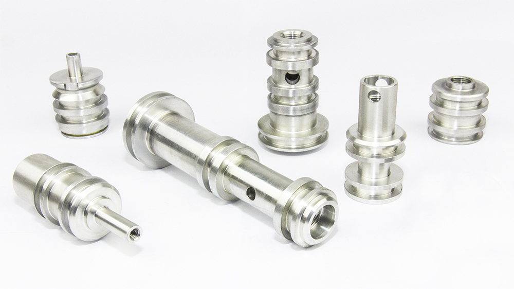
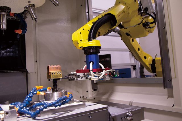
Mechanical Integration: This encompasses the robot’s physical mounting (floor, pedestal, gantry), the design of the End-of-Arm Tooling (EOAT) or gripper, and the part presentation system (fixtures, conveyors, pallets). The EOAT must provide rigid, repeatable part location without marring critical surfaces—a discipline where JLYPT’s precision machining expertise is often applied to craft custom gripper jaws and fixture components.
-
Electrical & Control Integration: The nervous system of the cell. This involves wiring the robot’s controller and the CNC’s PLC to a common safety circuit and establishing a reliable communication protocol for interlocking signals (e.g., “Robot in Home,” “Machine Door Open,” “Fixture Clamped”).
-
Software & Programming Integration: The intelligence layer. This includes programming the robot’s paths, synchronizing its movements with the machine’s cycles, creating the human-machine interface (HMI), and integrating with higher-level plant systems.
Table 1: Technical Specification Matrix for CNC Robot Integration Components
| System Component | Key Specifications & Considerations | Impact on Cell Performance | Integration Challenge |
|---|---|---|---|
| Industrial Robot | Payload (kg), Reach (mm), Repeatability (±mm), IP Rating, Mounting (floor, rail). | Determines part size capability, cell footprint, and speed. Accuracy affects part placement into fixture. | Matching robot kinematics and work envelope to the machine’s loading zone and part buffers. |
| CNC Machine Tool | Door/Window Size, Control Type (Fanuc, Siemens, Heidenhain), Available I/O Points, Pallet System Compatibility. | Defines the physical and digital interface for the robot. A large door and built-in pallet changer simplify integration. | Often the limiting factor. Retrofitting older machines with automation interfaces can be costly. |
| End-of-Arm Tooling (EOAT) | Grip Force (N), Actuation Type (Pneumatic, Electric), Jaw Design, Weight, Compliance Features. | Most critical for reliability. Directly responsible for part positioning accuracy and preventing damage. | Custom design is almost always required. Must account for chip/coolant exposure and high-cycle fatigue. |
| Part Presentation System | Buffer Capacity, Fixturing Repeatability, Compatibility with Part Families. | Determines the cell’s autonomy (hours of unattended run time) and flexibility for different parts. | Designing quick-change fixtures or adaptive grippers to handle a range of parts cost-effectively. |
| Control & Communication | Safety PLC Rating (e.g., SIL 2), Communication Protocol (Profibus, Profinet, Ethernet/IP), HMI Capability. | Ensures safe, synchronized operation and provides operational data and diagnostics. | Creating a robust and failsafe interlock logic between two different vendor systems (robot & CNC). |
| Peripheral Systems | Chip Conveyor, Coolant System, Mist Collector, Part Detection Sensors. | Supports long-term unattended operation by managing the by-products of machining. | Ensuring peripherals do not interfere with robot paths and are also automated/self-cleaning where possible. |
Section 2: The Implementation Blueprint – A Phased Approach to CNC Robot Integration
A successful integration is a meticulous engineering project, not a simple installation. Follow this phased methodology.
Phase 1: Feasibility Analysis and Cell Design
-
Part Family Analysis: Identify the parts suitable for robotic tending. Key parameters: weight, dimensions, cycle time, batch size, and annual volume. Look for commonalities in fixturing points.
-
Process Mapping & Cycle Time Analysis: Create a detailed time-motion study of the current manual process. Then, simulate the robotic cycle. The goal is to ensure the robot’s load/unload time is less than the machine’s cut time to avoid creating a new bottleneck. Use offline robot simulation software (e.g., RoboDK, Fanuc ROBOGUIDE) for this.
-
Cell Layout Simulation: Model the entire cell in CAD. Check for robot reach limitations, collisions, and optimize the placement of buffers, the robot, and the CNC to minimize the robot’s non-productive travel time.
Phase 2: The Critical Communication Interface
The handshake between the robot and CNC is foundational. A standard interface might use 5 core digital I/O signals:
-
CNC to Robot: “Cycle Complete / Door Open”, “Fixture Ready”, “Error / Fault”.
-
Robot to CNC: “In Position / Part Loaded”, “Cycle Start Request”, “Robot Fault”.
More advanced integrations use fieldbus networks (Profinet, EtherCAT) for faster, richer data exchange, potentially including analog signals for adaptive control.
Phase 3: Safety System Integration (Non-Negotiable)
A CNC robot integration cell is a guarded space. Safety must be architected to standards like ISO 10218-1/2 and ISO 13849-1.
-
Physical Safeguarding: Perimeter fencing with interlocked access gates. The cell must not operate if a gate is open.
-
Functional Safety: A safety-rated PLC or dedicated safety controller monitors emergency stops, safety gates, and light curtains. It must independently disable robot motion and CNC cycle start.
-
Risk Assessment: A formal risk assessment (per ISO 12100) must be conducted to identify and mitigate all hazards, including crushing, shearing, and entanglement.
Section 3: The Economics of Integration – Quantifying the Value of CNC Robot Integration
The business case extends far beyond labor displacement. It is an investment in asset productivity.
H3: The OEE Transformation
Overall Equipment Effectiveness (OEE) = Availability x Performance x Quality.
-
Availability: CNC robot integration directly attacks downtime. It eliminates manual loading delays, reduces break-related stoppages, and enables lights-out operation. Availability improvements of 15-30% are common.
-
Performance: Robots work at a consistent, programmed pace, eliminating the natural variance and slowdowns of human operators over a long shift.
-
Quality: Automated, repeatable part handling minimizes errors (wrong part, misload) and reduces damage from manual drops or improper clamping.
Return on Investment (ROI) Calculation
A comprehensive ROI model must include:
-
Hard Cost Savings: Direct labor reduction (wages, benefits). Reduced scrap/rework from handling errors. Lower consumable costs (gloves, etc.).
-
Soft Cost Savings & Revenue Enablement: Increased machine capacity (allows taking on more work without capital expenditure). Improved consistency leading to higher quality premiums. Ability to run unattended shifts (2nd/3rd shift) without labor cost.
-
Implementation Costs: Robot, EOAT, safety fencing, engineering, programming, installation, and training.
Table 2: Comparative ROI Analysis: Manual vs. Integrated Robotic CNC Operation
| Financial & Operational Metric | Manual CNC Machining Cell | Integrated Robotic CNC Cell | Financial Impact & Justification |
|---|---|---|---|
| Labor Cost per Shift | High (1 dedicated operator per 1-2 machines). | Low to Moderate (1 technician can monitor 4-8 robotic cells). | Direct savings. Labor is reallocated to higher-value tasks like programming and setup. |
| Machine Utilization (Uptime) | 50-70% (includes loading, breaks, delays). | 85-95% (continuous operation, lights-out possible). | Asset productivity gain. Effectively increases capacity of existing capital equipment. |
| Typical Scrap/Rework Rate | 2-5% (influenced by human error in loading/clamping). | <1% (repeatable, automated process). | Quality cost savings. Significant for high-value aerospace or medical components. |
| Consumable & Tooling Wear | Variable, can be higher due to inconsistent clamping. | Highly consistent, leading to predictable tool life and lower variance. | Indirect cost reduction. Enables more predictive maintenance and tool management. |
| Initial Capital Investment | Limited to machine tool cost. | High. Includes robot, tooling, safety, integration engineering. | Major capital outlay. Payback period typically 12-36 months depending on shift model. |
| Production Scalability | Linear: Adding output requires adding labor. | Non-linear: Adding a 2nd/3rd shift adds output with minimal added labor cost. | Enables growth without proportional labor increase. Improves business scalability. |
| Response to Demand Surge | Slow, constrained by labor market and training time. | Fast. Additional capacity is “switched on” by extending unmanned hours. | Strategic agility. Provides a competitive advantage in volatile markets. |
Section 4: Case Studies in CNC Robot Integration Excellence
Case Study 1: High-Volume Automotive Component Manufacturer
-
Challenge: A Tier 1 supplier machining aluminum transmission cases faced high labor costs and inconsistency across three shifts. Machine utilization was stuck at 65%.
-
Solution: A turnkey CNC robot integration for a bank of 5 horizontal machining centers (HMCs). Each cell featured a heavy-duty 6-axis robot on a linear rail serving two machines. A central pallet conveyor system delivered standardized fixtures with raw castings and removed finished ones. The integration included automatic door operation, fixture clamping confirmation, and in-station part probing cycle initiation.
-
Outcome: The system achieved 22.5 hours of unmanned operation per day. Machine utilization soared to 90%. Labor was reduced from 15 operators across 3 shifts to 3 technicians. The project achieved ROI in 22 months based on labor savings and throughput increase alone.
Case Study 2: Aerospace Job Shop – High-Mix, Low-Volume Flexibility
-
Challenge: A shop specializing in complex aerospace brackets needed to automate but was deterred by the high cost of dedicated fixturing for hundreds of low-volume part numbers.
-
Solution: Implementation of a flexible CNC robot integration cell using a collaborative robot (cobot) with a dual-mode gripper and a 2D vision system. The cell used a standardized vacuum chuck fixture plate. The cobot was programmed to pick raw blanks from a cart, load them onto the chuck, and initiate the CNC program. For finished parts, it would unload and place them in a designated tote. The vision system compensated for blank placement variance.
-
Outcome: While not achieving full lights-out, the cell eliminated the ergonomic strain of repetitive loading for machinists, freeing them for simultaneous operation of another machine. Changeover between different bracket families took under 5 minutes (changing the CNC program and vacuum fixture layout). The shop reported a 40% increase in output per machinist and a dramatic reduction in operator fatigue.
Case Study 3: Medical Implant Producer – Superalloy Machining Cell
-
Challenge: Machining cobalt-chrome and titanium orthopedic implants required extreme precision and cleanliness. Manual handling introduced contamination risk and variability in delicate part placement.
-
Solution: A cleanroom-compliant CNC robot integration cell was developed. A small, high-repeatability 6-axis robot with a sanitary-designed electric gripper was enclosed in a positive-pressure environment. The system integrated with a high-precision CNC mill and an in-process vision measurement system. The robot handled the parts using only designated tooling surfaces, placing them directly into cleaning and passivation baskets post-machining.
-
Outcome: The automated cell eliminated human-borne contamination, a critical FDA requirement. Part placement repeatability ensured consistent machining results. Full traceability was maintained as the robot logged every handling event. The capital investment was justified by the dramatic reduction in quality assurance overhead and the ability to meet stringent audit trails.
Conclusion: Architecting the Future-Proof Machine Shop
CNC robot integration is the definitive step towards building a resilient, data-driven, and highly productive manufacturing operation. It is a technical discipline that demands expertise in robotics, CNC machining, controls engineering, and safety systems. The journey requires careful planning, from part selection and cycle time analysis to the meticulous design of grippers and communication protocols.
The reward, however, is a fundamental transformation of your production economics. You shift from a variable-cost, labor-dependent model to a fixed-cost, asset-utilization model. The machine shop evolves from a collection of standalone tools into a network of automated production units, responsive to digital commands and optimized for maximum output.
For manufacturers embarking on this path, success hinges on detailed preparation and often, collaboration with partners who understand both the machining process and the integration challenge. At JLYPT, our deep CNC machining expertise provides the essential foundation for designing integration solutions that are not just automated, but are precision-engineered to protect part quality and maximize process reliability.
Ready to transform your machining capacity through strategic CNC robot integration? Contact JLYPT to begin a technical assessment of your production workflow. Discover our capability-driven approach at JLYPT CNC Machining Services.