Introduction: The Convergence of Precision and Aerospace Demands
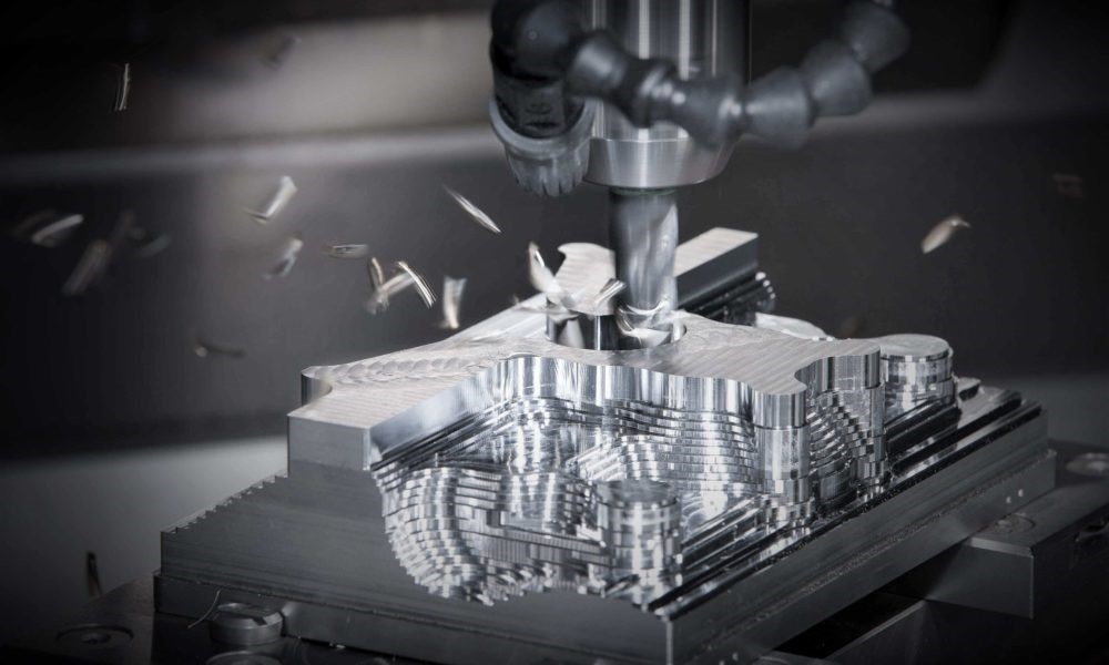
The aerospace industry operates at the forefront of engineering innovation, where the tolerances are tight, the materials are challenging, and the margin for error is zero. At the heart of manufacturing critical components for propulsion, airframes, and navigation systems lies high-precision CNC milling, a subtractive manufacturing process that has become indispensable. For engineers and procurement specialists navigating the complex supply chain, the selection of a machining partner is a strategic decision with far-reaching implications for performance, safety, and project viability. This article delves into the exacting world of aerospace-grade CNC milling, exploring the advanced capabilities, material expertise, and stringent quality control protocols that define top-tier service providers. We will examine how technologies like 5-axis simultaneous machining and micron-level accuracy are pushing the boundaries of what’s possible, enabling the creation of complex geometries from superalloys and composites that were once deemed unmachinable. Furthermore, we will explore the growing synergy between CNC milling and Additive Manufacturing (AM), where hybrid approaches are unlocking new design freedoms and manufacturing efficiencies. Through detailed case studies and technical breakdowns, we aim to provide a comprehensive resource for professionals seeking to understand the critical role of precision machining in lifting aerospace innovation off the drawing board and into the sky.
1. The Aerospace Mandate: Why Precision is Non-Negotiable
The operating environment of an aerospace component is arguably the most hostile on Earth and beyond. From the intense vibrations and acoustic loads during launch to the extreme thermal gradients and pressure differentials experienced at cruising altitude, every element must perform flawlessly. This relentless pursuit of reliability and performance dictates every aspect of manufacturing.
-
Weight Reduction: The “buy-to-fly” ratio is a critical metric in aerospace manufacturing. It represents the amount of raw material purchased versus the weight of the final finished part. A high ratio indicates significant waste through machining. Precision CNC milling is pivotal in achieving a low ratio by enabling the design and manufacture of complex, lightweight structures like thin walls, ribbed sections, and deeply pocketed features from a solid block of material, all while maintaining structural integrity. Every gram removed translates to substantial fuel savings and increased payload capacity over the lifespan of an aircraft or spacecraft.
-
Structural Integrity: Components such as engine mounts, landing gear assemblies, and actuation systems are subject to immense cyclical loads. The fatigue life of these parts is paramount to safety. High-precision machining ensures superior surface finishes and eliminates microscopic imperfections or residual stresses that can serve as initiation points for fatigue cracks. The precise control over geometry guarantees optimal fit and function, distributing stresses as intended by the design.
-
Aerodynamic Performance: The efficiency of turbines, compressors, and the airframe itself is heavily dependent on aerodynamic surfaces. The surface finish and dimensional accuracy of airfoils, blades, and vanes directly impact airflow, turbulence, and ultimately, thrust and fuel efficiency. CNC milling can produce these complex, often free-form surfaces, to tolerances that are impossible to achieve with conventional manual machining.
-
Extreme Environment Operation: Aerospace components must function reliably in conditions that would cause standard parts to fail immediately. This includes exposure to extreme temperatures, corrosive fluids, and high radiation. The materials chosen for these applications, such as titanium alloys and nickel-based superalloys, are notoriously difficult to machine. Precision CNC milling, with advanced toolpaths and cooling strategies, is essential for processing these materials without inducing damage that could compromise their innate properties.
2. Beyond 3-Axis: The Critical Role of 5-Axis CNC Machining
While 3-axis milling is sufficient for many applications, the complex geometries of aerospace components demand a more advanced approach. 5-axis CNC machining has become the industry standard for high-value, mission-critical parts.
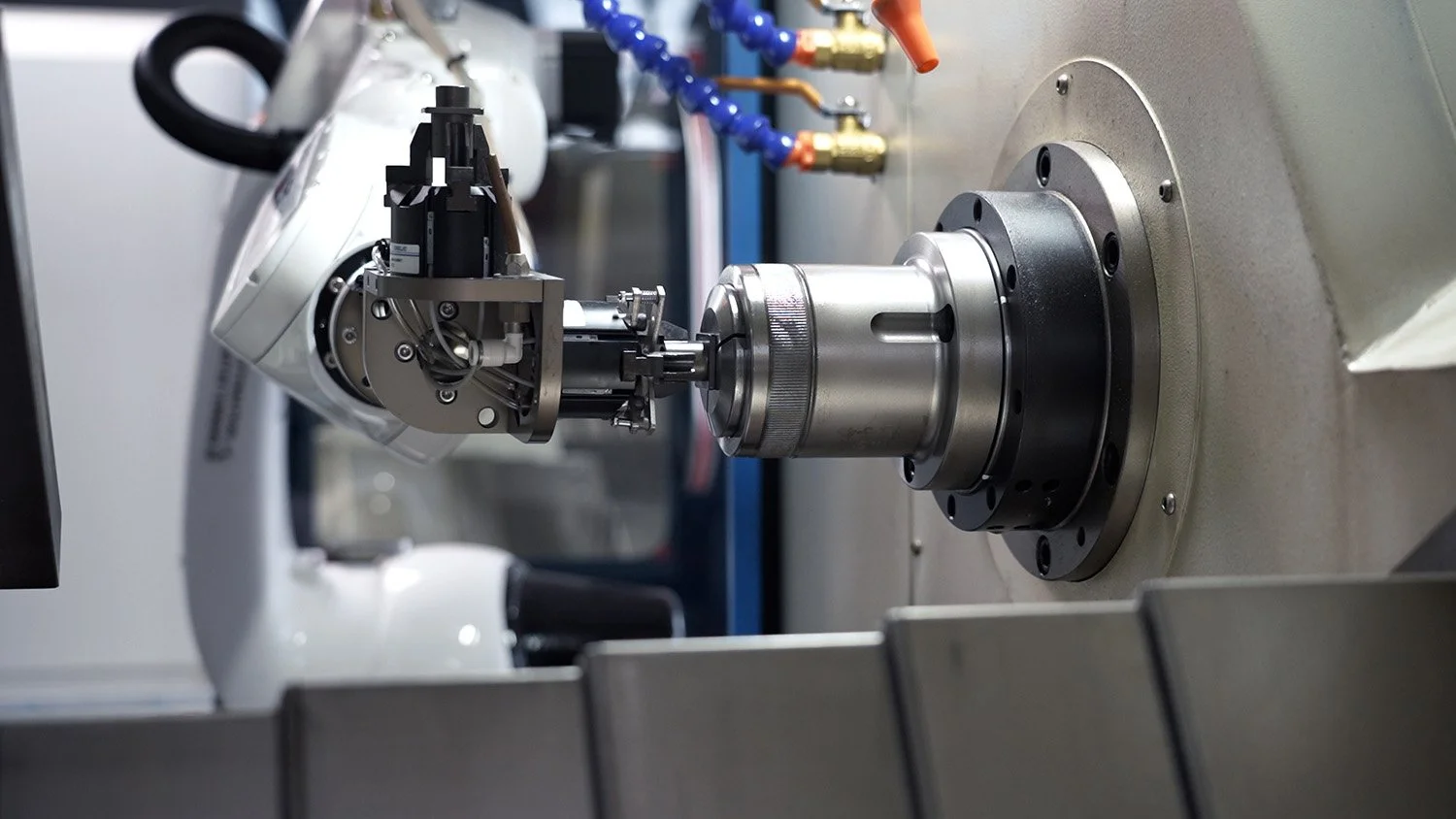
A 5-axis machine operates with three linear axes (X, Y, Z) and two rotational axes (A, B or C), often referred to as a rotary-tilt table or a trunnion configuration. This allows the cutting tool to approach the workpiece from virtually any direction in a single setup.
Advantages of 5-Axis Machining in Aerospace:
| Feature | Benefit for Aerospace Manufacturing |
|---|---|
| Single Setup Machining | Eliminates errors from multiple re-fixturing. Reduces total processing time and improves overall accuracy. |
| Improved Tool Access | Allows machining of complex, organic geometries like impellers, blisks, and structural brackets with deep pockets and undercuts. |
| Superior Surface Finish | The tool can maintain an optimal lead angle relative to the surface, allowing for shorter tools, reduced vibration, and better chip evacuation. |
| Enhanced Accuracy | By minimizing setup changes, datum transfer errors are virtually eliminated, ensuring features have true positional accuracy to one another. |
| Shorter Tools | The ability to tilt the workpiece brings it closer to the tool, allowing the use of shorter, more rigid cutters that deflect less, improving accuracy and surface finish. |
Technical Deep Dive: Machining an Aerospace Blisk
A blisk (bladed disk) is a quintessential aerospace component found in modern jet engines and compressors, perfectly illustrating the need for 5-axis machining.
-
Process: A solid forging of a material like Ti-6Al-4V or Inconel 718 is mounted on a 5-axis machine.
-
Roughing: The initial roughing operation uses barrel mills in a trochoidal milling path to quickly and efficiently remove large volumes of material between each blade airfoil.
-
Semi-Finishing: A second operation follows the approximate airfoil geometry, leaving a small, consistent stock allowance for the finishing pass.
-
Finishing: A long, tapered ball-nose end mill is used in a simultaneous 5-axis path. The machine dynamically adjusts the tool’s orientation to maintain the ideal cutting contact point and stepover between passes, achieving the required aerodynamic surface finish (often better than Ra 0.8 μm). The entire blisk, with its complex, shrouded geometry, is completed in one setup.
3. Material Science: Machining Advanced Aerospace Alloys
The properties that make aerospace alloys ideal for flight also make them exceptionally difficult to machine. Understanding these materials is key to selecting the right machining partner.
-
Titanium Alloys (e.g., Ti-6Al-4V):
-
Properties: High strength-to-weight ratio, excellent corrosion resistance, and good high-temperature performance.
-
Machining Challenges: Poor thermal conductivity causes heat to concentrate at the tool-workpiece interface, leading to rapid tool wear and work hardening. Its low modulus of elasticity can lead to part deflection during machining if not properly supported. It is also chemically reactive at high temperatures, which can lead to galling and adhesion to the cutting tool.
-
Our Approach: Using sharp, positive-rake geometry tools with specialized PVD coatings (like AlCrN). Employing high-pressure coolant (≥1000 psi) directed precisely at the cutting edge to break up chips and remove heat. Utilizing lower cutting speeds and higher feed rates to manage heat generation.
-
-
Nickel-Based Superalloys (e.g., Inconel 718, Waspaloy):
-
Properties: Retain high strength and corrosion resistance at extreme temperatures (up to 700°C+).
-
Machining Challenges: These materials exhibit high work hardening, high cutting forces, and abrasive carbide particles within their microstructure. They are notorious for causing notching and plastic deformation of cutting tools.
-
Our Approach: Using rigid setups and machines with high horsepower. Employing tough, micro-grain carbide substrates with MQL (Minimum Quantity Lubrication) or high-pressure coolant. Utilizing consistent feeds to “stay ahead of the heat” and avoid working in a hardened zone.
-
-
Aluminum Alloys (e.g., 7075, 2024):
-
Properties: Low density, good strength, and excellent machinability.
-
Machining Challenges: While easier to machine, achieving fine surface finishes and maintaining precise dimensional stability on thin-walled structures requires expertise. Built-up edge on tools can be an issue.
-
Our Approach: Using sharp, polished flute tools designed for aluminum. High-speed machining (HSM) strategies with high spindle speeds and feed rates are employed to achieve high material removal rates and excellent surface finishes.
-
Table: Aerospace Material Machining Guide
| Material | Typical Applications | Key Machining Strategies | Expected Surface Finish (Ra) |
|---|---|---|---|
| Ti-6Al-4V | Engine blades, structural brackets, fasteners, landing gear | High-pressure coolant, low RPM, high feed, sharp tools | 0.4 – 0.8 μm |
| Inconel 718 | Turbine disks, engine casings, exhaust systems | MQL, rigid setup, moderate speeds/feeds, tough carbide tools | 0.4 – 0.8 μm |
| Aluminum 7075 | Aircraft fuselage frames, wing ribs, mounting plates | High-speed machining, sharp polished tools, air blast | 0.2 – 0.6 μm |
| Stainless Steel 17-4PH | Landing gear components, actuators, engine fittings | Sharp tools, consistent feed, appropriate coolant | 0.3 – 0.6 μm |
4. The Digital Thread: From CAD to CMM
Precision machining is no longer just about the cutting tool; it’s about the seamless flow of digital information—the digital thread—that governs the entire process.
-
Design for Manufacturability (DFM): The process begins long before a tool touches metal. Our engineers analyze your CAD model (typically in STEP or IGES format) to identify potential manufacturing issues, such as inaccessible features, sharp internal corners, or excessively thin walls. We provide feedback to optimize the design for both function and manufacturability.
-
CAM Programming: Using advanced Computer-Aided Manufacturing (CAM) software, the 3D model is translated into a toolpath program (G-code). For aerospace parts, this involves:
-
Selecting optimal tooling and cutting parameters.
-
Generating efficient, smooth toolpaths like adaptive clearing and morphing to minimize tool wear and machining time.
-
Performing virtual machining simulations to detect any errors, collisions, or inefficiencies before the program is ever sent to the machine tool.
-
-
In-Process Monitoring: On the shop floor, modern CNC machines are equipped with probes and sensors. Tool setting probes automatically measure tool length and diameter offsets. Workpiece probes can locate a part datum and even perform first-article inspection on the machine, ensuring the part is correctly positioned and within tolerance before full production begins.
-
Post-Process Validation: After machining, parts move to the quality lab for rigorous inspection using Coordinate Measuring Machines (CMM). The CMM, programmed with the original CAD data, measures the part’s geometry and creates a detailed report comparing every feature to its nominal dimensions. For complex free-form surfaces, laser scanners may be used to create a point cloud for comparison against the CAD model, generating a full color map deviation report.
5. Case Studies: Precision in Action
Case Study 1: Satellite Propulsion System Housing
-
Challenge: Machine a complex, lightweight housing from a solid block of Aluminum 7075. The part featured numerous thin walls (0.5mm), deep pockets, and critical sealing surfaces requiring a tight tolerance of ±0.025 mm and a surface finish of Ra 0.4 μm.
-
Solution: A 5-axis CNC milling center was used with a specialized vacuum fixture to secure the part without inducing clamp-induced distortion. A high-speed machining (HSM) strategy was employed using a 0.25mm diameter end mill for finishing the thin walls. The machining process was simulated to predict and counteract any potential tool deflection.
-
Result: The part was produced to spec, passing all helium leak checks for the sealing surfaces. The single-setup process ensured perfect alignment of all port features, and the digital inspection report was provided with the delivered part.
Case Study 2: Turbine Engine Blade Tip Seal Segment
-
Challenge: Machine a Cobalt-based superalloy seal segment with a complex array of cooling holes that must be drilled at extreme compound angles. The part required a high-density pattern of holes with a diameter of 0.4mm ±0.012mm and exceptional surface finish to manage airflow.
-
Solution: The part was mounted on a precision 5-axis tilting rotary table. Using ultra-high-pressure coolant (1000+ bar) and solid carbide micro-drills, the CNC program dynamically oriented the part to the exact required angle for each hole. The process included peck drilling and frequent tool changes to ensure hole quality and prevent tool breakage.
-
Result: All cooling holes were produced within the specified diameter and true position tolerances. The part met the engine manufacturer’s stringent requirements for airflow and thermal performance.
Case Study 3: UAV (Unmanned Aerial Vehicle) Primary Structure
-
Challenge: Reduce the weight of a primary wing spar by 35% while maintaining its structural strength and stiffness. The initial design was a simple milled plate.
-
Solution: Our engineering team collaborated with the customer to redesign the spar using generative design principles. The new design featured an organic, lattice-like structure. The part was machined from a block of carbon fiber reinforced polymer (CFRP) composite using a diamond-coated tool on a high-speed 5-axis machine with specialized dust extraction.
-
Result: The final milled component achieved a 40% weight reduction and passed all structural load tests. This demonstrates how advanced CNC milling can be used to create complex, optimized structures typically associated with Additive Manufacturing, but with the material properties and surface finish of a traditional composite part.
6. The Synergy of CNC Milling and Additive Manufacturing (AM)
The rise of Additive Manufacturing (AM), or 3D printing, has not replaced CNC milling; rather, the two technologies have formed a powerful symbiotic relationship, especially in aerospace prototyping and production.
-
AM for Preforms, CNC for Precision: A common hybrid approach is to use Laser Powder Bed Fusion (L-PBF) or Directed Energy Deposition (DED) to build a near-net-shape preform of a part. This preform is then finished using high-precision CNC milling to achieve critical dimensions, tight tolerances, and the necessary surface finish on mating surfaces, holes, and datums. This combines the design freedom and material efficiency of AM with the unparalleled accuracy of CNC.
-
Tooling and Fixturing: AM is extensively used to produce complex, lightweight jigs and fixtures that are then used on CNC machining centers to hold complex aerospace parts for milling. These custom fixtures can reduce setup time and improve accuracy.
Key AM Terminology in Aerospace:
-
Additive Manufacturing (AM): The process of joining materials to make parts from 3D model data, usually layer upon layer.
-
Rapid Prototyping (RP): Using AM to quickly produce a physical model of a part for form, fit, or functional testing.
-
Rapid Tooling (RT): The use of AM to create molds, patterns, or fixtures for use in manufacturing processes.
-
STL (Standard Tessellation Language): The common file format used by AM systems, which describes the surface geometry of a part using triangles.
-
Support Structures: Temporary structures generated to support overhanging features during the AM build process, which are later removed.
Conclusion: Soaring on the Wings of Precision
The relentless pursuit of performance, safety, and efficiency in the aerospace industry is fundamentally underpinned by advancements in high-precision CNC milling services. It is a discipline that seamlessly blends cutting-edge machinery, deep materials science expertise, and rigorous process control to transform the most resilient advanced alloys into the components that enable flight. As aerospace systems evolve towards increased complexity and integration, the role of the machining partner becomes ever more critical.
The future points towards even greater integration—the hybrid additive and subtractive manufacturing cell, where a part can be built, measured, and finished in a single, automated environment. Machine learning and AI-driven adaptive control will further optimize toolpaths in real-time, compensating for tool wear and material variability to achieve unprecedented levels of quality and consistency.
Choosing a supplier like JL YPT means partnering with a team that understands this complex landscape. We are not just machine operators; we are engineering partners committed to providing the micron-level accuracy, uncompromising quality, and technical collaboration required to make your most ambitious aerospace projects take flight.
Ready to experience the difference that true precision machining can make for your aerospace components? Contact JL YPT today to request a comprehensive quote or to discuss your specific project requirements with our engineering team.
