
How Do Robotic Arms Work: The Precision Mechanics Behind CNC Automation
Introduction: The Pivotal Role of Robotic Arms in Modern Manufacturing
In the high-stakes environment of precision CNC machining, where component tolerances are measured in microns and spindle uptime directly translates to profitability, the industrial robotic arm has evolved from a novel automation tool to an indispensable production asset. For machine shops and contract manufacturers, understanding the intricate question—how do robotic arms work—is not merely technical curiosity; it is a strategic necessity. This knowledge informs smarter purchasing decisions, enables more effective programming and maintenance, and unlocks the full potential of automated work cells. As a leader in precision CNC machining services, JLYPT recognizes that the synergy between advanced multi-axis machining centers and sophisticated robotics creates a competitive edge that is both technological and operational.
At its core, the operation of a robotic arm is a symphony of mechanical engineering, real-time computation, and sensor feedback. It is a closed-loop system designed to translate digital commands into flawless, repeatable physical motion. This process encompasses everything from the high-level path planning generated by CAD/CAM software down to the micro-adjustments of a servo motor compensating for load inertia. This comprehensive guide will deconstruct the robotic arm, layer by layer. We will examine its mechanical architecture, the core principles of its movement and control, and the critical integration points that allow it to work in concert with CNC machine tools to perform complex tasks like high-speed tending, precision deburring, and even direct machining.
Part 1: The Mechanical Architecture – The Arm’s Physical Foundation
The mechanical structure of a robotic arm determines its fundamental capabilities: its reach, its strength, its speed, and its precision. Most industrial robots used in machining environments are articulated robots, featuring a serial-link design that mimics the mobility of a human arm.
1.1 The Kinematic Chain: Links and Joints
The arm is constructed as a chain of rigid bodies called links, connected by articulating joints. Each joint provides one degree of freedom (DOF).
-
Base (Link 0): The fixed foundation, securely mounted to the factory floor, a pedestal, or a linear track.
-
Links (Arm Segments): The upper arm, forearm, and wrist components. Their geometry, material (often lightweight aluminum or carbon composite), and internal ribbing are engineered for maximum stiffness-to-weight ratio, minimizing deflection under load.
-
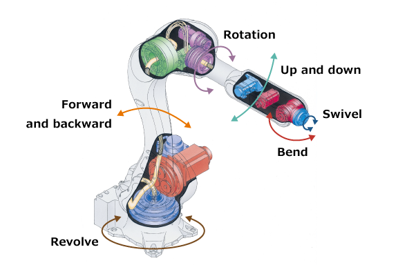
Joints (Axes 1-6): These are almost exclusively revolute joints (rotational) in articulated arms.
-
Axis 1 (Waist): Rotates the entire arm at the base.
-
Axis 2 (Shoulder): Controls the major vertical movement of the upper arm.
-
Axis 3 (Elbow): Governs the extension and retraction of the forearm.
-
Axes 4-6 (Wrist): A compact, three-axis assembly (roll, bend, swivel) that provides the final orientation of the end-effector. This design, known as a spherical wrist, is crucial for achieving complex tool orientations required in 5-axis machining operations.
-
1.2 Actuation and Transmission: Creating Motion
Motion at each joint is generated by an actuator, typically a brushless AC servo motor, known for its high torque, precision, and responsiveness. However, servo motors operate at high rotational speeds with relatively low torque. To convert this into the powerful, precise, and slower movement needed at the joint output, a reduction gear is essential.
-
Harmonic Drive Gears: Prevalent in compact wrist axes, these gears offer extremely high reduction ratios, near-zero backlash, and high torque capacity in a lightweight package. Their minimal backlash is critical for achieving high positional repeatability.
-
RV (Rotary Vector) Reducers: Common in the larger base, shoulder, and elbow joints, RV reducers provide exceptional rigidity, high torque, and excellent shock load resistance, making them ideal for heavy-duty material handling in machining cells.
-
Direct Drive Motors: An emerging technology that eliminates the gearbox entirely, coupling the motor directly to the joint. This removes backlash completely and simplifies maintenance but requires specialized, high-torque motors.
1.3 The End-Effector: The Interface to the Task
The end-effector, or End-of-Arm Tooling (EOAT), is the device attached to the robot’s wrist that interacts with the workpiece or machine. In CNC environments, this is far more than a simple gripper. It can be:
-
A custom mechanical gripper with hardened steel jaws for holding raw billets.
-
A vacuum matrix system for handling large, flat sheet metal or finished machined surfaces.
-
A motorized spindle unit for robotic drilling, milling, or deburring.
-
A tool changer mechanism that allows a single robot to switch between different grippers and process tools, enabling flexible, multi-operation cells.
Table 1: Core Mechanical Components of an Industrial Robotic Arm
| Component Category | Specific Elements | Primary Function | Impact on CNC Machining Performance |
|---|---|---|---|
| Structural Frame | Base, Upper Arm Link, Forearm Link, Wrist Housing. | Provides the rigid kinematic chain; defines the work envelope and static load capacity. | Determines maximum part size and weight that can be handled; structural stiffness influences machining accuracy under load. |
| Joint & Actuation System | Servo Motor, Brake, Harmonic Drive/RV Reducer, Output Flange, High-Precision Bearings. | Converts electrical energy into controlled rotational motion at each axis. | Gearbox backlash directly affects repeatability; motor torque defines acceleration and payload capacity. |
| Feedback Sensors | Multi-Turn Absolute Encoder (per motor), Resolver. | Provides real-time, high-resolution data on joint position, speed, and acceleration to the controller. | Encoder resolution is fundamental to achieving micron-level repeatability for precision placement and tool paths. |
| End-Effector Interface | ISO 9409 Standard Tool Flange, Pneumatic/Electric Utility Ports, Quick-Change Coupler. | Provides the mechanical, electrical, and pneumatic connection for EOAT. | Enables rapid changeover between different machining or handling tasks; ensures secure, repeatable tool mounting. |
Part 2: The Control System – The Brain and Nervous System
The mechanical arm is a sophisticated puppet; the robot controller is the puppeteer. This industrial computer is responsible for planning, executing, and monitoring every aspect of the arm’s movement.
2.1 Controller Hardware Architecture
The controller is a specialized, ruggedized computer system.
-
Main CPU: Executes the robot’s operating system, runs the user interface, and performs high-level motion planning.
-
Servo Drives: One for each axis motor. These are sophisticated amplifiers that receive a target position command from the CPU and, using continuous feedback from the motor’s encoder, adjust voltage and current to the motor in real-time to hit the target. This forms a closed-loop servo control system.
-
Safety Controller: A separate, certified Programmable Safety System (PSS) that monitors emergency stops, safety gate interlocks, and speed/position limits to ensure safe operation per ISO 10218 standards.
-
I/O Modules & Fieldbus Interfaces: Handle all communication with the external world. Digital I/O signals manage discrete actions (e.g., “Gripper Close,” “CNC Door Open”). Fieldbus networks like PROFINET, EtherCAT, or EtherNet/IP enable high-speed, deterministic data exchange with CNC controls, PLCs, and sensor systems.
2.2 The Kinematic Engine: Translating Thought into Motion
At the mathematical heart of the controller is the kinematic model. This software model is a digital twin of the arm’s physical geometry (link lengths, joint offsets). It performs two critical calculations:
-
Forward Kinematics: Given the angles of all joints, calculate the precise position and orientation (pose) of the Tool Center Point (TCP) in 3D space. This is used for simulation and live position display.
-
Inverse Kinematics (IK): The essential calculation for operation. Given a desired TCP pose (from a programmed path), calculate the set of joint angles required to achieve it. For a 6-axis arm, there are often multiple solutions; the IK solver chooses the optimal one based on efficiency and the need to avoid singularities—special configurations where the robot loses a degree of freedom and control becomes problematic.
2.3 Programming and Path Execution
Robots are programmed using manufacturer-specific languages (e.g., KUKA KRL, FANUC TP, ABB RAPID) or graphical offline programming (OLP) software.
-
Motion Instructions: Commands like
PTP(Point-to-Point) for fast, joint-coordinated moves andLIN(Linear) for straight-line TCP movement are the building blocks.LINmoves are crucial for machining applications where the tool must follow a precise linear or contoured path. -
Path Interpolation & Look-Ahead: The controller doesn’t simply jump from point to point. It creates a smooth, continuous trajectory. Look-ahead functionality analyzes dozens of programmed points in advance, dynamically optimizing velocity and acceleration to maintain path accuracy while minimizing cycle time and mechanical vibration—a vital feature for high-quality surface finishing.
Part 3: Sensory Feedback and Adaptive Control
To move beyond simple, repetitive tasks and operate intelligently in the variable environment of a machine shop, robotic arms rely on a suite of sensors.
3.1 Internal State Sensing
-
Motor Encoders: The primary source of feedback, providing the data that makes closed-loop servo control possible. Modern absolute encoders maintain position data even after a power loss, eliminating the need for homing sequences.
3.2 External World Sensing
-
Force/Torque Sensors: Mounted at the wrist between the flange and the EOAT, these sensors measure the forces and torques applied to the tool. This enables compliant motion control. For example, during robotic deburring, the controller can maintain a constant contact force regardless of part tolerances, or during assembly, it can perform a delicate insertion by “feeling” the alignment.
-
2D/3D Vision Systems: Cameras provide spatial awareness. In a fixed-mount configuration, they can identify and locate parts on a conveyor. In an eye-in-hand configuration (camera mounted on the wrist), the robot can perform precise inspection, verify feature presence, or guide a tool along a seam with visual servoing.
-
Laser Trackers and Metrology Systems: Used for high-precision applications like aerospace drilling, these external systems provide real-time feedback on the TCP’s absolute position in space, allowing the controller to correct for minute deflections or thermal drift, achieving accuracies normally reserved for CNC machine tools.
Table 2: From Command to Motion: The Robotic Control Loop in a Machining Context
| Process Stage | System/Component Involved | Action Performed | Example in CNC Tending |
|---|---|---|---|
| High-Level Command | Offline Programming (OLP) Software / Teach Pendant. | A path is created: “Move to Machine Door, then to Fixture at coordinates (X,Y,Z), then retract.” | Program defines the pick-and-place cycle for a finished machined part. |
| Path Planning & IK Solve | Controller’s Main CPU & Kinematic Engine. | Converts the Cartesian path into a time-sequenced series of setpoints for each joint axis. | Calculates how Axis 1-6 must move in coordination to achieve a smooth arc into the CNC machine’s work area. |
| Servo Loop Execution | Individual Servo Drive for each Axis. | Compares the target joint position with the actual position from the encoder and adjusts motor current to minimize error. | Axis 3 (Elbow) servo makes micro-corrections to maintain perfect trajectory despite the inertia of the payload. |
| Peripheral Coordination | Controller I/O & Fieldbus Network. | Sends/outputs signals to interact with the CNC and EOAT. | Sends a “Part Unclamped” signal to the fixture, then a “Gripper Close” command to the pneumatic valve bank. |
| Real-World Adaptation | Force Sensor / Vision System. | Provides feedback that modifies the pre-planned path in real-time. | Force sensor detects a misaligned part during insertion, triggering a search pattern to find the correct location. |
Part 4: Integration with CNC Machining – Creating a Cohesive Cell
The ultimate value of a robotic arm in precision manufacturing is realized through its seamless integration with CNC equipment. This transforms standalone machines into automated, flexible manufacturing cells.
4.1 Machine Tending: The Foundational Application
This is the most common application, where the robot acts as an autonomous operator.
-
Synchronization: Integration is achieved via I/O handshaking or direct Fieldbus communication (e.g., FANUC FOCAS, Siemens SINUMERIK Integrate). A typical sequence involves the robot requesting the CNC to open its door, the CNC confirming the door is open and the spindle is safe, the robot executing the load/unload, and finally signaling the CNC to start the next cycle.
-
Impact: This enables lights-out manufacturing, dramatically increasing spindle utilization and overall equipment effectiveness (OEE).
4.2 Robotic Machining and Finishing
Here, the robot transitions from a handler to a machine tool platform.
-
Direct Machining: For large parts (e.g., composite aircraft components, large molds), a high-stiffness robot equipped with a spindle can perform trimming, routing, and drilling. The challenge is the robot’s lower static stiffness compared to a CNC gantry. This is mitigated through advanced path calibration, vibration damping software, and the use of kinematic models that compensate for load-induced deflection.
-
Adaptive Finishing: Robots excel at repetitive, skill-intensive finishing work. A robot with a force-controlled spindle or grinding tool can deburr, polish, and blend surfaces with unerring consistency, adapting in real-time to part variations.
4.3 In-Process Metrology and Quality Control
Robots bring flexibility to quality assurance.
-
Automated Inspection: A robot can be programmed to present every machined part to a touch probe or laser scanner at an inspection station. The collected data is logged for statistical process control (SPC) and can even be fed back to the CNC for automatic tool wear compensation.
Part 5: Case Studies – Principles in Action
Case Study 1: High-Volume Production of Automotive Transmission Housings
-
Challenge: A Tier 1 supplier needed to machine aluminum transmission housings on a transfer line with multiple CNC stations. Manual loading was a bottleneck and ergonomic risk.
-
Solution & How the Arm Works: A heavy-payload 6-axis robot was installed on a linear track parallel to the transfer line. The robot’s controller was synchronized with the line’s PLC. Using precise linear (LIN) moves, the robot would pick a raw casting from a pallet, place it into the first machining station’s hydraulic fixture, and signal the clamp to close. As the part progressed down the line, the robot would move on its track to unload and reload subsequent stations. The robot’s servo motors and RV reducers provided the strength for the heavy parts, while its kinematic model allowed it to calculate the precise angle needed to insert the part into each unique fixture without collision.
-
Outcome: The system achieved full automation of the line, increasing throughput by 35% and eliminating manual handling injuries.
Case Study 2: Precision Robotic Deburring of Aerospace Turbine Blades
-
Challenge: The complex, airfoil geometry of investment-cast turbine blades required consistent deburring of all edges—a tedious, manual process with variable results.
-
Solution & How the Arm Works: A robotic cell was built with a 6-axis arm equipped with a spindle and a proprietary deburring tool. A 6-axis force/torque sensor was installed at the wrist. The toolpath was generated from the blade’s CAD model. During operation, the robot executed the path using its standard position control. Simultaneously, the force control loop continuously read the sensor. If the tool pressed too hard, the controller generated a slight positional offset command, telling the arm to back off. This hybrid position/force control allowed the robot to maintain perfect, programmed contact pressure along the entire variable contour of the blade, adapting to casting tolerances in real-time.
-
Outcome: The cell achieved 100% consistency in edge quality, eliminated manual labor from a difficult task, and provided digital records of the force profile for each part.
Case Study 3: Flexible, High-Mix Machining Cell for a Job Shop
-
Challenge: A contract machining shop serving the medical and aerospace sectors needed to automate but could not dedicate robots to single machines due to low batch sizes and high part mix.
-
Solution & How the Arm Works: The shop implemented a mobile robotic unit: an autonomous guided vehicle (AGV) carrying a collaborative robot (cobot) and a set of tooling. The AGV would navigate to a CNC machine requiring service. The cobot, using its integrated vision system, would locate the machine’s door handle and fixture. Using hand-guiding, the machinist would quickly teach the cobot the load/unload points for a new part. The cobot’s inherent force-limiting safety design allowed it to work without safety cages, sharing space with the machinist for setup. The cobot’s controller, while less powerful than an industrial controller, still performed all the essential inverse kinematics and servo control to execute the taught points reliably.
-
Outcome: The shop gained flexible automation. One robotic asset could service multiple machines, making automation economical for high-mix production. The ease of programming via hand-guiding allowed for quick changeovers, key to the shop’s business model.
Conclusion: Mastering Motion for Manufacturing Excellence
Understanding how do robotic arms work reveals a remarkable integration of physics, computer science, and electrical engineering. From the robust harmonics of a gear reducer to the millisecond calculations of an inverse kinematics solver, each component plays a critical role in creating intelligent, purposeful motion. For manufacturers, this knowledge is power. It enables informed dialogues with integrators, fosters effective troubleshooting, and illuminates the path to more sophisticated applications.
The trajectory is clear: robotic arms are becoming more perceptive, more connected, and more precise. Technologies like AI-driven path optimization, digital twin simulation, and cloud-based analytics are building upon the foundational principles of mechanics and control discussed here. At JLYPT, our expertise in precision CNC machining services is complemented by a deep appreciation for these automation principles. We engineer solutions where the extreme accuracy of our 5-axis mills and EDM systems is matched by the intelligent, reliable motion of robotic partners, creating manufacturing cells that are not just automated, but truly optimized for the future.
Ready to integrate precision motion into your manufacturing process? Contact JLYPT to discuss how robotic automation, grounded in solid engineering principles, can elevate your production capabilities. Explore our commitment to advanced manufacturing at JLYPT CNC Machining Services.


