
Quadcopter Frame CNC Cutting: A Shop‑Floor CNC Machining Playbook for Stiff, Light, Repeatable Frames
A quadcopter frame is a structural system, not a collection of plates. The frame determines how well the aircraft holds geometry under thrust loads, how the flight controller “sees” vibration, how reliably the stack aligns, and how fast field repairs can be performed. A frame that looks correct in CAD can still be noisy, hard to assemble, or inconsistent across builds if the manufacturing strategy is not engineered.
That’s why Quadcopter frame CNC cutting is more than “cut the outline and drill holes.” It includes:
- choosing the right material system (CFRP plate, aluminum billet, hybrid)
- selecting a CNC process (router cutting, VMC milling, 4/5‑axis when needed)
- building a datum strategy that matches real assembly
- controlling fiber breakout, burrs, and plate warp
- managing tolerances that matter (true position, flatness, perpendicularity)
- planning finishing and inspection so production remains stable
This article is written for engineers, product managers, and sourcing teams who want a frame that builds cleanly and flies consistently. It is also written for anyone who has been burned by “almost identical” plates that don’t quite align—forcing hand reaming, slotting, or overtightened screws that crack carbon.
If you’re sourcing production CNC UAV components, JLYPT supports custom manufacturing programs here:
https://www.jlypt.com/custom-cnc-uav-parts-manufacturer/
Table of Contents
- What “Good” Looks Like in Quadcopter Frames
- Quadcopter frame CNC cutting: Frame Architectures and What They Demand from Machining
- Material Choices (CFRP, G10, 6061, 7075, Titanium)
- Core Components to CNC Cut/Machine (Plates, Arms, Motor Mounts, Brackets)
- CNC Process Routes: Router Cutting vs VMC Milling vs Hybrid
- Tooling and Parameters: Chip Load, Tool Geometry, and Edge Quality
- Fixturing & Workholding: Vacuum, Tabs, Onion Skin, and Distortion Control
- Hole-Making Quality: Drilling, Reaming, Thread Milling, and Inserts
- GD&T and Datum Planning for Stack Alignment and Motor Geometry
- Surface Finish, Deburr, Edge Sealing, and Coatings
- Inspection Plans: CMM, Flatness, Hole Position, and Assembly Gauges
- Cost Drivers and RFQ Checklist
- Detailed Tables (DFM, Process Routing, Tolerance Priorities, QC Gates)
- Three Case Studies
- Why JLYPT for Quadcopter frame CNC cutting
- External Reference Links (DoFollow)
1) What “Good” Looks Like in Quadcopter Frames
A frame can be “strong” and still be a bad frame if it couples vibration into the stack, creeps out of alignment after a few hard landings, or varies between batches. In production reality, a good frame is:
- Geometrically repeatable: motor-to-motor distances and diagonals are consistent
- Assembly-friendly: standoffs start by hand, holes align without forcing, fasteners seat flat
- Stiff where needed: arms resist torsion; stack area stays flat
- Predictable in vibration: resonance is managed rather than randomly shifting
- Repairable: arms or motor mounts can be replaced without scrapping the entire chassis
Most of those outcomes are manufacturing outcomes. Quadcopter frame CNC cutting determines whether you get crisp edges, accurate hole position, consistent thickness, and stress-free assembly.
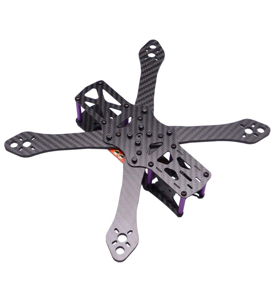
2) Quadcopter frame CNC cutting: Frame Architectures and Machining Implications
Different frame architectures lead to different machining constraints. A freestyle FPV frame is often crash-tolerant and modular; a mapping quad wants stiffness and low vibration; a heavy-lift platform needs robust interfaces and predictable load paths.
Table 1 — Frame Architectures vs CNC Cutting/Machining Requirements
| Frame Architecture | Typical Use | Key Performance Goal | CNC Cutting/Machining Focus | Common Failure if Mis-Made |
|---|---|---|---|---|
| “Sandwich” plate stack (top/bottom + arms) | FPV freestyle, racing | crash repair, low cost | fast plate cutting + accurate arm interfaces | hole misalignment causes arm twist and vibration |
| Unibody carbon bottom plate | performance FPV | stiffness + weight | delamination control, flatness control | edge cracking near motor holes |
| Aluminum hub + carbon arms | industrial, custom builds | robust center + replaceable arms | hybrid machining, controlled datum | arm-to-hub skew shifts motor angles |
| Fully machined aluminum frame | harsh environment | durability | pocketing strategy, warp control | plate distortion, heavy weight if not optimized |
| Foldable arms (hinged) | portable ops | packability | accurate hinge bores + wear surfaces | hinge slop, poor repeatability |
For each architecture, Quadcopter frame CNC cutting must be planned around the “critical interfaces,” not the outline geometry.
3) Material Choices for Frames (and What They Do to the CNC Plan)
Frame performance begins with materials. But manufacturability matters just as much—especially at scale.
Table 2 — Material Selection for Quadcopter Frames
| Material | Strength-to-Weight | Machinability | Typical CNC Method | Notes for Frame Designers |
|---|---|---|---|---|
| CFRP plate (carbon fiber laminate) | excellent | specialized | CNC routing / high-speed cutting | control dust + delamination; edge sealing recommended |
| G10/FR4 | good | easier than CFRP | CNC routing | more forgiving, heavier, good for prototypes |
| 6061‑T6 aluminum | good | excellent | CNC milling (VMC) | stable, anodizes well, cost-effective |
| 7075‑T6 aluminum | very good | good | CNC milling | higher strength; more sensitive to stress risers |
| Titanium (selected interfaces) | high | difficult | milling/turning | use selectively (wear parts), rarely for full frames |
For CFRP, Quadcopter frame CNC cutting is as much about process discipline as it is about geometry: tool choice, feed strategy, and edge management often decide whether parts look “production” or look chipped.
4) What You Actually CNC Cut or Machine in a Quadcopter Frame
Frames are systems. Even if your primary “frame” is CFRP plates, you still need machined components for interfaces: standoff bosses, clamps, motor mounts, camera cages, antenna mounts, quick-release mechanisms, etc.
Table 3 — Quadcopter Frame Parts and the Typical CNC Process
| Part | Material (Common) | Primary Process | Critical-to-Quality (CTQ) Features |
|---|---|---|---|
| Bottom plate | CFRP / G10 / aluminum | CNC cutting (router) or milling | flatness, hole true position, edge integrity |
| Top plate | CFRP / aluminum | CNC cutting or milling | stack hole alignment, camera mount alignment |
| Arms | CFRP / aluminum | CNC cutting or milling | motor hole pattern, arm thickness, torsional stiffness |
| Motor mount plates | aluminum | milling | flatness, hole pattern, spotfaces |
| Stack standoff blocks | aluminum | milling | perpendicularity, thread quality |
| Camera cage / side plates | CFRP / aluminum | cutting/milling | slot width, hole alignment, edge finish |
| Hardware (pins, sleeves) | stainless/titanium | turning | diameter tolerance, surface finish |
| Vibration isolation parts | polymer | milling | pocket depths, consistent fit |
A frequent manufacturing mistake is to treat the “plate cutting” as low-precision work. In reality, Quadcopter frame CNC cutting sets the reference geometry for everything that bolts to it.
5) CNC Process Routes: Router Cutting vs VMC Milling vs Hybrid
The right route depends on material, thickness, tolerance, and volume.
5.1 CNC Router Cutting (CFRP/G10 plates)
Strengths:
- fast profiling
- efficient nesting (sheet utilization)
- excellent for 2D plate geometry
Constraints:
- fiber breakout risk
- edge finish consistency depends heavily on tooling and feeds
- dust management is mandatory
5.2 VMC Milling (Aluminum plates and hubs)
Strengths:
- tight tolerances and excellent feature control
- strong for pocketing, threaded features, spotfaces, datum surfaces
- robust inspection correlation
Constraints:
- more expensive per part if geometry is mostly 2D outlines
- thin plates can warp if the toolpath is aggressive
5.3 Hybrid Approach (Common in premium frames)
A practical production method is:
- router-cut CFRP plates
- machine aluminum hubs, clamps, cages, and standoff blocks on VMC
- use turning for sleeves/pins This hybrid method keeps Quadcopter frame CNC cutting efficient while still putting precision where it matters.
Table 4 — Process Selection Guide for Quadcopter Frame CNC Cutting
| Requirement | Best Process | Why |
|---|---|---|
| High volume 2D CFRP plate shapes | CNC routing | speed + nesting |
| Tight hole position across multiple features | VMC milling + drilling/reaming | rigid control |
| Deep pockets / ribs in aluminum | VMC milling | stiffness + stability |
| Precision cylindrical sleeves/pins | CNC turning | roundness + finish |
| Complex multi-face hub | 4/5-axis milling | fewer setups, better datum control |
6) Tooling and Parameters: Chip Load, Tool Geometry, and Edge Quality
This is where many frame programs succeed or fail. Frames are thin, and thin parts amplify cutting forces and chatter. Quadcopter frame CNC cutting needs a disciplined approach to tooling.
6.1 CFRP / G10 tooling considerations
- compression cutters can reduce top/bottom edge fray
- PCD or diamond-coated tools improve tool life and edge quality
- climb cutting often improves finish (verify with your setup and laminate)
- dust extraction is not optional; it affects both quality and safety
6.2 Aluminum tooling considerations
- maintain proper chip load to avoid rubbing (heat = warp + poor finish)
- reduce tool stick-out to maintain stiffness
- use adaptive clearing for pockets to maintain constant tool engagement
- plan finish passes for critical edges and datum faces
Table 5 — Practical Tooling Choices for Quadcopter Frame CNC Cutting
| Material | Operation | Tool Type | Common Quality Risk | Shop Control Lever |
|---|---|---|---|---|
| CFRP | profile cut | compression end mill | delamination, fuzzing | tool wear monitoring + correct feed |
| CFRP | holes | brad-point / specialized drill | breakout at exit | backup support + correct peck cycle |
| G10 | profile cut | carbide end mill | melting/tearing | dust extraction + sharp tool |
| 6061 | pocketing | carbide end mill | chatter on thin areas | adaptive toolpath + support fixturing |
| 7075 | drilling | carbide drill | burrs, tool wear | spot drill + optimized SFM |
If you’re aiming for consistent production results, treat tool wear as a measurable variable. In Quadcopter frame CNC cutting, edge quality changes quickly once a CFRP tool dulls.
7) Fixturing & Workholding: Vacuum, Tabs, Onion Skin, and Flatness Control
Fixturing decides whether plates stay flat and whether hole locations remain stable. With thin plates, clamping can distort parts before the first toolpath even runs.
7.1 Vacuum tables and spoil boards (plate cutting)
For CFRP plates, vacuum workholding is common:
- supports the entire sheet
- reduces clamp obstruction
- helps reduce vibration during contouring
7.2 Tabs vs onion skin
- Tabs: small uncut bridges that keep the part attached; removed later
- Onion skin: leave a thin layer, then final pass to free the part Onion skin often improves edge quality because the last pass is light and controlled—useful for Quadcopter frame CNC cutting when you want clean perimeter edges.
7.3 Flatness control in aluminum plates
Thin aluminum plates tend to move as internal stresses release. Techniques:
- symmetric pocketing strategy
- finish critical faces last
- leave machining allowance for a final skim cut
- use a fixture plate that supports the whole surface
Table 6 — Workholding Problems and Fixes
| Symptom | Likely Cause | Better Workholding | Better Toolpath / Sequence |
|---|---|---|---|
| plate “potato chips” after machining | stress + uneven removal | full support fixture | rough both sides symmetrically |
| hole pattern shifts across runs | inconsistent datum | pinned datum + probing | machine key holes in same setup |
| CFRP edge frays intermittently | sheet vibration | stronger vacuum + support | reduce stepdown, add finishing pass |
| small parts fly loose | insufficient retention | onion skin + final release | add tabs or controlled cut-out |
This is a core point: Quadcopter frame CNC cutting is often a workholding project disguised as a cutting project.
8) Hole-Making Quality: Drilling, Reaming, Thread Milling, and Inserts
If a frame builds poorly, it’s often because holes are inconsistent: burrs, positional error, or out-of-round holes that cause screws to “pull” parts into alignment—creating stress and vibration.
8.1 Drilling and reaming
- Drill for location and speed
- Ream for size and roundness when you need precision fits (dowels, hinge pins, sleeves)
8.2 Thread milling (preferred for high-value aluminum parts)
Thread milling can reduce tap break risk and improve consistency, especially in 7075 or when threads are close to an edge.
8.3 Inserts for serviceability
Frames that are meant to be repaired benefit from inserts in:
- soft aluminum threads that will see repeated disassembly
- camera cage mount points
- arm replacement interfaces
Table 7 — Hole and Thread Strategy for Quadcopter Frames
| Feature | Recommended Method | Why | Inspection Method |
|---|---|---|---|
| motor hole pattern (M2/M3) | drill + deburr | clean seating | go/no-go + visual |
| stack holes | drill + position control | alignment of flight stack | CMM or functional gauge |
| dowel/sleeve holes | drill + ream | repeatable location | pin gauge + CMM |
| critical threads in aluminum | thread milling or inserts | service life | thread gauge + torque audit |
| CFRP holes | specialized drilling with backup | reduce breakout | visual + pin gauge |
Good hole-making is a major contributor to “premium feel.” It’s also a direct output of Quadcopter frame CNC cutting discipline.
9) GD&T and Datum Planning (So Frames Assemble Straight)
If you want interchangeable parts and consistent builds, you need datums that mirror assembly reality.
GD&T framework reference (DoFollow):
https://www.iso.org/standard/63175.html
General tolerances concept reference (DoFollow):
https://www.iso.org/standard/29183.html
Surface texture reference (DoFollow):
https://www.iso.org/standard/52075.html
9.1 Practical datum scheme for a plate-based quadcopter frame
A production-friendly method:
- Datum A: bottom plate primary plane (stack reference)
- Datum B: one locating hole (or dowel hole) near the stack
- Datum C: a second feature to clock rotation (another hole or edge)
9.2 What to control (and what not to over-control)
High value controls:
- flatness of the stack area plane
- true position of stack hole pattern relative to datum A/B/C
- true position of motor hole patterns relative to arm reference datums
- perpendicularity of standoffs/bosses relative to datum A
Avoid wasting tolerance budget on:
- non-functional outer edges (unless aesthetic is critical)
- internal lightening pocket radii (unless they drive stress)
Table 8 — GD&T-to-Function Map (Frame Context)
| Feature | Function | Suggested Control | Why It Matters |
|---|---|---|---|
| bottom plate plane | stack stability | flatness | reduces IMU vibration coupling |
| stack holes | assembly alignment | true position | prevents forced assembly |
| arm interface holes/slots | motor geometry | true position | preserves diagonal symmetry |
| motor mount face | motor alignment | flatness / perpendicularity | reduces yaw drift and vibration |
| standoff threads | assembly | position + thread spec | repeatable stack preload |
A repeatable datum strategy reduces rework, and it makes Quadcopter frame CNC cutting measurable instead of subjective.
10) Surface Finish, Deburr, Edge Sealing, and Coatings
10.1 CFRP edges: sealing matters
CFRP edges can absorb moisture and damage layers if left rough. Many premium builds include:
- careful deburr (non-aggressive)
- edge sealing (depending on laminate and use environment)
10.2 Aluminum frames: anodize-aware design
If you anodize aluminum parts:
- plan for coating thickness in fits (especially bores and tight pockets)
- mask critical electrical contacts if required
- define cosmetic class so production doesn’t get stuck chasing non-functional marks
Table 9 — Finish Recommendations for Quadcopter Frame CNC Cutting
| Material | Area | Best Practice | Common Mistake |
|---|---|---|---|
| CFRP | perimeter edges | light deburr + controlled finish pass | sanding aggressively and weakening edges |
| CFRP | holes | backer support + light chamfer | leaving sharp edges that start cracks |
| aluminum | motor mount face | finish pass, verify flatness | bead blast distorting functional faces |
| aluminum | threads | clean + protect | coating buildup inside fine threads |
| mixed | fastener seating | controlled spotfaces | fasteners “rocking” due to uneven seating |
11) Inspection Plans: Make Quality Visible
Even a great machining process drifts without measurement. A practical plan focuses on CTQs.
Table 10 — Inspection Plan Template (Production-Friendly)
| CTQ | Tool | Frequency | Release Criteria |
|---|---|---|---|
| plate thickness | micrometer | per batch | within spec; check variation |
| flatness (stack zone) | surface plate + indicator / CMM | FA + sampling | within flatness tolerance |
| hole true position (stack) | CMM / functional gauge | FA + sampling | must assemble without forcing |
| motor hole pattern | CMM or template gauge | sampling | consistent fit, no elongation |
| edge integrity (CFRP) | visual standard | 100% visual | no delam, no major fray |
| thread quality | GO/NO-GO | 100% critical | pass gauges |
For CFRP, add a visual acceptance standard for delamination and fiber breakout. For aluminum, add a quick torque audit for threaded joints in high-load areas.
12) Cost Drivers and RFQ Checklist
12.1 What actually drives cost in Quadcopter frame CNC cutting
- tight positional tolerances on many holes
- multi-operation setups (flip parts, align, re-probe)
- cosmetic requirements on CFRP edges and chamfers
- tool wear (CFRP) and scrap risk (thin plates)
- post-process work (deburr, seal edges, anodize, assembly)
12.2 RFQ checklist (send this with your drawings)
- 3D CAD + 2D drawings with datums and CTQs defined
- material spec (CFRP type/thickness, aluminum grade/temper)
- finish requirements (edge finish, anodize type/color, sealing needs)
- target quantities (prototype / pilot / production)
- inspection/report requirements (FAI, CMM report, sampling plan)
- packaging requirements (CFRP scratch protection, flatness protection)
The faster you clarify CTQs, the faster Quadcopter frame CNC cutting stabilizes in production.
13) Detailed Tables (DFM, Process Routing, Tolerance Priorities, QC Gates)
Table 11 — DFM Rules That Prevent Common Frame Problems
| DFM Rule | Why | Better Outcome |
|---|---|---|
| keep adequate edge distance for holes | reduces crack initiation in CFRP and tearing in aluminum | stronger arms and motor mounts |
| avoid sharp internal corners in high-stress zones | stress risers lead to fatigue and cracking | better crash survivability |
| define spotfaces for fastener heads | stable clamp load, less loosening | consistent assembly torque |
| avoid long unsupported thin webs | chatter + warping | better dimensional control |
| consider modular arms | faster repair, less scrap | better field maintainability |
Table 12 — Example Process Routing (CFRP Bottom Plate)
| Op # | Step | Machine | Key Control | Typical Risk | Control Plan |
|---|---|---|---|---|---|
| 10 | sheet prep + ID | prep | laminate orientation + traceability | mixing thickness/layup | labeling + traveler |
| 20 | vacuum fixture setup | router | full support | vibration | leak check + spoilboard |
| 30 | rough contour + pocketing | router | stable cutting | delamination | sharp tool + correct feed |
| 40 | drill holes | router/drill | breakout control | frayed exits | backer + optimized cycle |
| 50 | finish contour pass | router | edge quality | fuzzing | light finish pass |
| 60 | part release (onion skin) | router | controlled release | edge chip | final shallow pass |
| 70 | deburr/edge finish | bench | consistent standard | over-sanding | work instruction + samples |
| 80 | final inspection | QC | CTQ check | missed delam | 100% visual + gauge |
Table 13 — Example Process Routing (6061 Aluminum Hub / Stack Plate)
| Op # | Step | Machine | Key Control | Typical Risk | Control Plan |
|---|---|---|---|---|---|
| 10 | rough mill | VMC | datum creation | warp | balanced stock removal |
| 20 | semi-finish pockets | VMC | avoid thin-wall chatter | chatter | adaptive toolpaths |
| 30 | drill/ream key holes | VMC | position + size | drift | probing + tool offsets |
| 40 | thread milling | VMC | thread quality | oversize/undersize | gauge + torque sample |
| 50 | finish skim | VMC | flatness | distortion | finish last, light pass |
| 60 | deburr | bench | no sharp edges | burrs | deburr map |
| 70 | anodize (if required) | finishing | thickness control | fit issues | masking + post-fit check |
| 80 | final QC | CMM/gauges | CTQ release | escapes | CTQ checklist |
Table 14 — “Spend Tolerance Where It Pays” (Frame Edition)
| Feature | Tolerance Priority | Reason |
|---|---|---|
| stack hole pattern | very high | controls electronics alignment |
| motor hole patterns | very high | controls thrust symmetry |
| plate flatness near IMU | high | influences vibration behavior |
| outer profile | medium | aesthetics + clearance |
| lightening pocket radii | low | non-critical for assembly |
14) Three Case Studies (Prototype → Production Lessons)
Case Study 1 — FPV Freestyle Frame: CFRP Unibody Bottom Plate With Repeated Arm Cracks
Problem: A unibody CFRP bottom plate looked great, but cracks initiated near motor holes after repeated hard landings. Builders also reported inconsistent edge quality between batches.
Manufacturing fix (Quadcopter frame CNC cutting focused):
- revised cutting strategy: added a controlled finish contour pass and limited stepdown to reduce edge fray
- implemented tool-life limits (replace before visible fuzzing appears)
- improved hole drilling method with backer support to reduce breakout at exit
- updated DFM: increased edge distance and adjusted corner radii to reduce stress concentration
Result: Crack initiation rate dropped noticeably in field use, and edge finish became consistent enough that post-sanding time decreased.
Case Study 2 — Industrial Quadcopter: Aluminum Hub + Carbon Arms With Alignment Drift
Problem: The aircraft showed yaw trim differences between units. Investigation found slight skew at the arm-to-hub interface, forcing arms into alignment during assembly and storing stress in the structure.
Manufacturing fix (Quadcopter frame CNC cutting + machining interface control):
- introduced a datum-based machining sequence for the hub: created datum A/B/C early and kept critical holes in a single setup
- added true position control for arm interface holes and verified with CMM on first articles
- added spotfaces so fasteners seated consistently without “rocking”
- created a simple functional gauge to verify diagonal geometry before shipment
Result: Unit-to-unit alignment improved, assembly became “drop-in,” and yaw trim differences reduced because motor geometry was no longer being forced.
Case Study 3 — Mapping Quadcopter: Stack Plate Flatness and IMU Vibration Issues
Problem: The flight controller showed elevated vibration in certain RPM bands. The stack plate was thin to save weight and sometimes came out slightly warped after pocketing, changing how isolation grommets loaded.
Manufacturing fix (Quadcopter frame CNC cutting and warp control):
- changed pocketing strategy to constant engagement and reduced cutting forces
- supported the plate on a full-contact fixture rather than edge clamping
- left a small finish allowance and performed a final light skim pass on the datum plane last
- added a flatness check on a surface plate as a QC gate
Result: Flatness became consistent across batches, and vibration behavior became more predictable. The tuning team stopped “chasing” mechanical variation.
15) Why JLYPT for Quadcopter frame CNC cutting
Quadcopter frame CNC cutting requires more than a capable machine. It requires a manufacturing plan that respects thin parts, composite edge integrity, datum control, and assembly repeatability—plus inspection that focuses on the geometry that actually affects flight.
JLYPT supports CNC UAV programs from prototype through production, including frame plates, arms, aluminum hubs, motor mount parts, camera cages, clamps, and precision hardware.
Start here (internal link you requested):
https://www.jlypt.com/custom-cnc-uav-parts-manufacturer/
Additional internal link:
16) External Reference Links (DoFollow)
- ISO GD&T framework (ISO 1101): https://www.iso.org/standard/63175.html
- General tolerance concept: https://www.iso.org/standard/29183.html
- Surface texture parameters: https://www.iso.org/standard/52075.html
- CFRP tensile testing reference: https://www.astm.org/d3039_d3039m-17.html


