
The Integral Role of Robot Kinematics in Modern CNC Machining
Introduction to Robotic Motion in Precision Manufacturing
In the world of precision manufacturing, the principles of robot kinematics have quietly revolutionized what’s possible in Computer Numerical Control (CNC) machining. While CNC machines and industrial robots may appear as distinct technologies, their operational cores share a fundamental language: the precise mathematical description and control of motion in three-dimensional space. At JLYPT CNC Machining, we leverage these synergies daily, applying kinematic principles not just to our multi-axis machining centers but to our entire automated manufacturing philosophy to deliver components with unprecedented precision, complexity, and efficiency.
Robot kinematics—the science of motion without considering forces—provides the mathematical framework for describing the position and orientation of a robot’s end effector (or a CNC machine’s tool head) relative to its base. This framework is equally vital for programming the sophisticated 5-axis and 7-axis CNC systems that produce the complex aerospace, medical, and automotive components our clients rely on. Understanding forward kinematics (predicting the tool position from joint angles) and inverse kinematics (calculating required joint angles to achieve a desired tool position) is what allows us to machine intricate geometries with tolerances as tight as ±0.005mm, transforming digital designs into flawless physical reality.
This article will explore the deep technical integration of kinematic principles within advanced CNC machining processes. We will examine how these concepts translate from theory to practice on the shop floor, enabling the production of parts that were once considered unmanufacturable, and solidify JLYPT’s position at the forefront of precision manufacturing innovation.
The Foundational Mathematics: From Theory to Toolpath
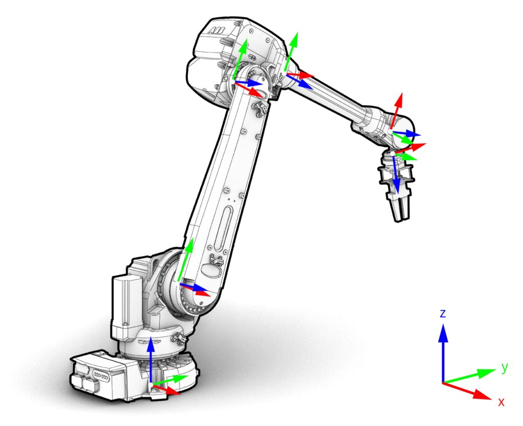
The journey from a CAD model to a finished machined part is governed by kinematics. Every CNC machine, from a 3-axis mill to a 7-axis hybrid machining center, is essentially a specialized robotic manipulator. Its structure—a series of links and joints—creates a kinematic chain. The machine controller uses kinematic models to translate G-code commands (linear and rotary movements) into the precise coordinated motions of each axis.
Forward Kinematics in CNC Context: In a 5-axis CNC milling setup, forward kinematics calculates the exact position (X, Y, Z) and orientation (A, B axes) of the cutting tool tip based on the known positions of all the machine’s linear slides and rotary tables. This is crucial for real-time tracking, collision avoidance, and ensuring the tool is where the program expects it to be.
Inverse Kinematics: The Programmer’s Engine: This is the workhorse for CAM (Computer-Aided Manufacturing) software. The programmer defines the desired toolpath over the workpiece. Inverse kinematics solves for the necessary combination of machine axis movements to keep the tool normal to the complex, contoured surface being machined. This allows for simultaneous 5-axis machining, where the tool can approach the workpiece from virtually any angle, enabling the production of monolithic components with deep pockets, undercuts, and complex organic shapes common in aerospace and automotive design.
The table below summarizes the core kinematic concepts and their direct applications in our CNC machining services at JLYPT:
Table 1: Core Kinematic Concepts and Their CNC Machining Applications
| Kinematic Concept | Mathematical Description | Primary CNC Application at JLYPT | Resulting Benefit |
|---|---|---|---|
| Forward Kinematics | Calculating end-effector (tool) pose from known joint parameters. | Real-time tool positioning verification and machine calibration. | Ensures machining accuracy and prevents costly collisions. |
| Inverse Kinematics | Calculating required joint parameters to achieve a desired end-effector pose. | Generating efficient toolpaths for 3+2 and simultaneous 5-axis machining. | Enables machining of complex, monolithic geometries in a single setup. |
| Denavit-Hartenberg (D-H) Parameters | A standardized method for assigning coordinate frames to kinematic chains. | Modeling and programming our 7-axis hybrid (milling + turning) machines. | Allows for seamless integration of milling and turning operations. |
| Workspace Analysis | Defining the complete set of positions reachable by the end-effector. | Process planning and fixture design to ensure part manufacturability. | Optimizes machine utilization and minimizes setup changes. |
| Singularity Avoidance | Identifying configurations where joint velocity becomes mathematically infinite. | Optimizing 5-axis toolpaths to maintain smooth, controlled motion. | Protects machine mechanics and ensures superior surface finish (down to Ra 0.4µm). |
Kinematic Architectures: How Machine Design Dictates Capability
The physical design of a CNC machine defines its kinematic structure, which in turn dictates its capabilities and limitations. At JLYPT, we operate a portfolio of machines with different kinematic architectures, each selected to optimally serve specific manufacturing challenges.
Serial Kinematics (The Traditional Robot Arm): Most CNC milling machines use a serial kinematic chain, where joints and links are connected end-to-end. A classic 3-axis vertical machining center (VMC) has three serial joints: the X, Y, and Z linear axes. This design offers a large workspace relative to its footprint. Our advanced 5-axis mills often employ a trunnion table (A and C rotary axes attached to the table) or a swivel head (two rotary axes on the spindle). While slightly less rigid than some alternatives, this serial configuration provides excellent flexibility and access for machining complex parts like turbine blades or injection molds.
Parallel Kinematics (The Hexapod): Exemplified by hexapod machines, this structure uses multiple independent kinematic chains (legs) connecting a fixed base to a moving platform (which holds the spindle). This design offers exceptional stiffness and agility, as the motors are mounted on the stationary base, reducing moving mass. It is ideal for high-speed, high-precision machining of aluminum alloy prototypes or for delicate operations on hardened materials like Inconel 718. The inverse kinematics for parallel machines is significantly more complex but allows for dynamic error compensation.
Hybrid Kinematics: Our most capable systems, such as 7-axis mill-turn centers, combine serial and parallel elements. They might feature a serial lathe spindle and tool turret integrated with a parallel-actuated milling spindle. This hybrid approach, programmed using sophisticated kinematic models, allows us to complete a part—requiring turning, milling, and off-center drilling—in a single chucking. This is critical for maintaining concentricity tolerances within ±0.02 mm for components like medical implant fixtures or optical housing units.
Case Studies: Kinematics Solving Real-World Manufacturing Challenges
The true value of applied robot kinematics is demonstrated not in theory, but in solving tangible production challenges. The following cases from JLYPT’s project portfolio illustrate this translation from mathematical principle to industrial advantage.
Case Study 1: Aerospace Turbine Casing with Integrated Mounting Lugs
-
Challenge: A client required a large, thin-walled titanium alloy turbine casing. The design included multiple mounting lugs positioned at compound angles on the outer diameter. Traditional 3-axis machining would require numerous complex, error-prone fixtures and setups.
-
Kinematic Solution: Our engineers utilized the inverse kinematics capabilities of our 5-axis gantry mill with a swivel-rotary head. The CAM system calculated a continuous toolpath where the machine’s X, Y, Z, A, and C axes moved simultaneously to keep the cutting tool perpendicular to the contoured surface at all times.
-
Outcome: The entire casing, including all angled lugs, was machined from a solid billet in a single setup. This eliminated cumulative fixture errors, reduced lead time by 60%, and ensured perfect alignment of all features. The dynamic control of tool orientation also allowed for optimal chip evacuation and tool life when machining the tough titanium alloy.
Case Study 2: High-Precision Medical Bone Plate with Bio-Compatible Surface
-
Challenge: A surgical bone plate made from medical-grade stainless steel required a complex, anatomically contoured geometry with a series of variable-angle, tapered screw holes. The final part needed a flawless electropolished finish for biocompatibility, demanding that the machined surface be completely free of tool marks or microscopic burrs.
-
Kinematic Solution: A 4-axis CNC machining center with a programmable rotary B-axis was employed. Inverse kinematics was used to generate a toolpath where the rotary axis precisely indexed the part for each screw hole, while the linear axes controlled the tapered mill. Singularity-aware path planning ensured smooth, jerk-free transitions between positions, which is paramount for achieving the required surface integrity.
-
Outcome: The bone plates were produced with perfect geometric and surface quality right off the machine, requiring only a final electropolishing pass. The kinematic precision of the toolpath resulted in a burr-free condition, a critical factor for medical implants. The process validated our capability to hold the demanding ±0.005mm tolerances required for life-critical devices.
Case Study 3: Automotive Lightweighting with a Complex Aluminum Structural Node
-
Challenge: An automotive manufacturer sought to reduce vehicle weight with a single, lightweight aluminum alloy node that replaced an assembly of ten welded steel brackets. The node had organic, topology-optimized internal webbing and external mounting faces on multiple non-orthogonal planes.
-
Kinematic Solution: This part was a perfect candidate for our 5-axis simultaneous machining on a machine with a tilting-rotary table (A and C axes). The kinematic model allowed the spindle to reach deep into the part’s internal cavities at the optimal angle, machining the intricate webbing in one operation. The workspace analysis ensured the large part would not collide with the machine column during these aggressive maneuvers.
-
Outcome: We delivered a monolithic component that reduced the subsystem’s mass by 45% while increasing its stiffness. The project demonstrated how advanced kinematics enables design for additive manufacturing (DfAM) principles to be applied via subtractive CNC machining, combining structural efficiency with the superior material properties of wrought aluminum.
The Synergy of Kinematics, Metrology, and Quality Assurance
Precision machining is meaningless without verification. At JLYPT, kinematic principles extend beyond the machining process into our quality assurance ecosystem. Our coordinate measuring machines (CMM) and laser scanners are themselves precision robotic arms. They use the same forward/inverse kinematic models to probe a finished part, collecting point cloud data that is compared against the original CAD model.
This creates a closed-loop kinematic chain: the digital model informs the machine kinematics, which produces the part, which is then measured by a metrology arm whose kinematics verify the outcome. Any deviation is analyzed, and its root cause—whether tool wear, thermal drift, or a fixture shift—can be diagnosed and corrected, often through compensation in the machine’s kinematic model. This rigorous process underpins our ISO 9001:2015 certified quality management system and is essential for achieving the sub-micron accuracy required in our CNC jig grinding and deep-hole boring (handling L/D ratios up to 30:1) services for the semiconductor and hydraulic industries.
Future Frontiers: Adaptive Kinematics and AI-Driven Machining
The future of CNC machining lies in making kinematic systems adaptive and intelligent. We are integrating sensor feedback (for force, vibration, and temperature) to create real-time adaptive control loops. Imagine a system where the machine’s inverse kinematics model is dynamically adjusted mid-cut based on actual cutting forces to optimize feed rate and prevent tool deflection, especially in long-reach scenarios common in mold and die making.
Furthermore, research into machine learning for singularity prediction and path optimization is ongoing. AI algorithms can learn from vast datasets of successful toolpaths to suggest novel, more efficient kinematic solutions for machining extremely complex geometries, such as those found in next-generation heat exchangers or custom orthopedic implants. This evolution will further blur the line between pre-programmed automation and intelligent, responsive robotic manufacturing.
Conclusion: Precision Engineered Through Motion
From the fundamental calculations that guide a tool’s journey to the sophisticated multi-axis machines that execute them, robot kinematics is the silent engine of modern high-precision CNC machining. It is the discipline that allows JLYPT to bridge the gap between ambitious engineering design and manufacturable reality. By mastering the mathematics of motion, we empower our clients to innovate without constraints, producing lighter, stronger, and more complex components for industries that define progress.
Whether you are pushing the boundaries of aerospace design, advancing medical technology, or revolutionizing automotive performance, the principles explored here are at work delivering your vision. For a partnership that understands motion, precision, and production at the most fundamental level, explore our comprehensive capabilities at JLYPT CNC Machining Services.


