Revolutionizing Precision Manufacturing: The Strategic Integration of Robotic Vision Systems in Modern CNC Machining
The relentless pursuit of perfection in precision manufacturing has entered a new era, defined not just by the capabilities of the machine tool itself, but by the intelligence that guides it. At JLYPT, a leader in advanced CNC machining services, we are at the forefront of this transformation by strategically integrating sophisticated Robot Vision Systems into our production ecosystem. This synergy is not merely an incremental upgrade; it is a paradigm shift that redefines the boundaries of accuracy, efficiency, and reliability in creating complex components.
This in-depth exploration will dissect the multifaceted role of robotic vision in CNC machining, moving beyond theoretical concepts to provide a detailed, technical analysis of its implementation, benefits, and tangible impact on the manufacturing workflow.
Deconstructing the Robot Vision System: More Than Just a Camera
A common misconception is that a Robot Vision System is simply a camera mounted on a robotic arm. In reality, it is a complex, integrated system of hardware and software designed to replicate and exceed human visual inspection capabilities in a industrial environment. The core components include:
-
Imaging Hardware: This encompasses high-resolution CCD/CMOS sensors, strategically chosen lenses (telecentric, macro, or standard), and advanced lighting systems (LED ring lights, backlights, structured light). The lighting is critical for eliminating shadows, enhancing contrast, and highlighting specific features like edges or surface defects.
-
Processing Unit: The “brain” of the operation. This is a high-speed industrial computer equipped with powerful frame grabbers and processors capable of executing complex image analysis algorithms in milliseconds.
-
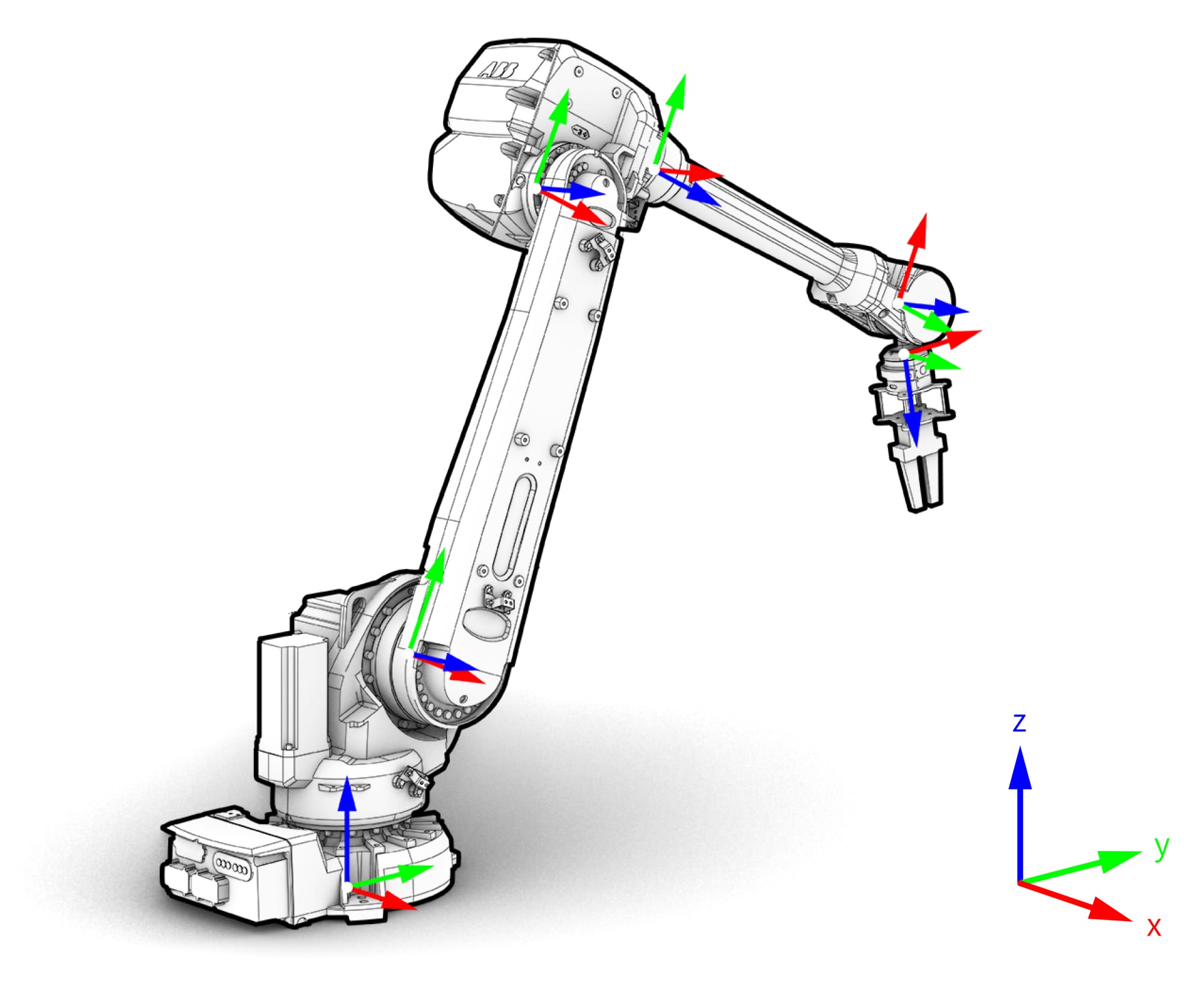
Robotic Actuator: Typically a multi-axis articulated robot (6-axis is common) or a precision gantry system, which provides the mobility and dexterity to position the vision sensor in optimal orientations for inspection or guidance.
-
Sophisticated Software: This is where the magic happens. The software utilizes machine vision libraries for tasks like pattern matching, blob analysis, edge detection, Optical Character Recognition (OCR), and, increasingly, deep learning-based AI models for classifying complex and variable defects.
The operational cycle is a continuous loop: The system captures an image, the software processes it based on pre-defined algorithms, a decision is made (e.g., “Pass/Fail,” “Feature Found at X,Y,Z”), and a command is sent to the robot or the CNC machine’s controller to execute a physical action.
The Strategic Imperative: Why Integrate Vision with CNC Machining?
The integration of vision systems addresses several critical challenges inherent in high-precision, low-volume, and complex-component manufacturing.
-
Closed-Loop Quality Assurance: Traditional post-process inspection is reactive. A part is machined, removed from the fixture, and taken to a CMM. Any error discovered at this stage means a scrapped part and lost time. An integrated Robot Vision System enables in-process inspection. The robot can probe critical dimensions between machining operations, allowing for real-time tool wear compensation or early error detection, effectively creating a closed-loop manufacturing system.
-
Overcoming Fixturing and Datum Challenges: For parts with complex geometries or those lacking traditional datum features, establishing a precise coordinate system can be time-consuming. Vision systems can perform “on-the-fly” part localization. By identifying specific features on a raw blank or a partially machined part, the system can update the CNC machine’s work offset (G54, G55, etc.), ensuring the toolpath aligns perfectly with the actual part position, irrespective of minor fixturing variances.
-
Enabling High-Mix, Low-Volume Production: The economic viability of manufacturing small batches relies on rapid changeover. A vision-guided robot can be quickly reprogrammed to handle different parts, using visual cues to identify the part type and select the correct inspection routine or machining program automatically. This drastically reduces setup times and makes flexible manufacturing a reality.
A Detailed Taxonomy of Robot Vision Applications in CNC Workflows
The applications can be categorized into three primary functions, each with distinct technical requirements and outcomes.
1. In-Process Metrology and Dimensional Verification
This is the most direct application, replacing or supplementing touch probes and manual gauging.
-
Application: Measuring critical features like bore diameters, thread presence, boss heights, and planar surfaces while the part is still clamped in the vise or fixture.
-
Technical Execution: The robot, equipped with a high-resolution camera and telecentric lens for minimal perspective error, moves to pre-programmed inspection points. The vision software performs sub-pixel edge detection to calculate dimensions with micron-level repeatability. The results are logged statistically, and if a measurement drifts outside the tolerance band (e.g., ±0.01mm), the system can flag the part or trigger an automatic tool offset in the CNC controller.
-
Advantage over Traditional Methods: Non-contact, much faster than CMM for a few critical dimensions, and prevents the machining of out-of-tolerance features, saving material and spindle time.
2. Automated Part Localization and Pick-and-Place
This application streamlines material handling and ensures machining accuracy from the very first operation.
-
Application: Picking raw material blanks or semi-finished parts from a bin or conveyor and loading them into a CNC machine with high precision.
-
Technical Execution: The vision system scans a bin of randomly oriented parts. Using 2D or 3D vision (often with a laser scanner), it identifies the position and orientation of the top part. It calculates the precise 3D coordinates and a rotation angle, transmitting this data to the robot. The robot then picks the part and places it into the machine fixture. The vision system can perform a final verification to confirm correct placement before machining commences.
-
Advantage over Traditional Methods: Eliminates the need for costly and rigid fixturing for feeding. Enables “lights-out” manufacturing for loading/unloading operations and drastically reduces the risk of misload crashes.
3. Post-Process Surface and Defect Inspection
This is a comprehensive final quality gate that goes beyond simple dimensions.
-
Application: Identifying surface defects such as tool marks, burrs, micro-cracks, cosmetic flaws, or ensuring the presence of all required features.
-
Technical Execution: The robot maneuvers the vision camera around the complex contours of the finished part, capturing images from multiple angles under consistent lighting. Advanced algorithms, including texture analysis and deep learning, are trained to identify anomalies that would be subjective or fatiguing for a human inspector.
-
Advantage over Traditional Methods: 100% inspection coverage, objective and consistent judgment, detailed digital records for traceability (Industry 4.0), and the ability to detect subtle defects invisible to the naked eye.
Technical Comparison: Vision Systems vs. Traditional Metrology
The following table provides a detailed comparison of key inspection and guidance methodologies.
Table 1: Comparative Analysis of Inspection & Guidance Methodologies
| Feature | Robot Vision System | Traditional CMM | Manual Inspection | Touch Probe (On-Machine) |
|---|---|---|---|---|
| Speed | Very High (ms per feature) | Slow (minutes to hours) | Moderate to Slow | Moderate |
| Contact | Non-Contact | Contact | Contact | Contact |
| In-Process Capability | Yes | No | No | Limited |
| Data Richness | High (2D/3D image data) | High (3D point cloud) | Low (Go/No-Go) | Moderate (3D points) |
| Flexibility | High (reprogrammable) | Low (fixed setup) | High | Low (within machine) |
| Operator Influence | None | Low | High | None |
| Ideal Use Case | High-speed in-process checks, surface defects, guidance | Final validation of critical geometric tolerances (GD&T) | Simple Go/No-Go checks, cosmetic review | In-machine datum setting, simple in-process checks |
| Capital Cost | Medium to High | High | Low | Low (often standard) |
Case Studies: Robot Vision in Action at JLYPT
Case Study 1: Zero-Defect Machining of Aerospace Manifold Blocks
-
Challenge: A client required complex aluminum manifold blocks with dozens of intersecting internal fluid passages. A single machining error on a deep bore would render the entire, expensive block scrap. Post-machining pressure testing was the only quality check, which was too late.
-
Solution: JLYPT integrated a Robot Vision System equipped with a micro-borescope camera. After each deep-hole drilling cycle, the robotic arm would insert the borescope into the passage. The vision software, using specialized optics and lighting, automatically verified the depth, diameter, and intersection accuracy of the bore. It also checked for any unacceptable tooling witness marks.
-
Result: The system identified a slight deviation in tool wear on one drill after 50 parts, allowing for proactive tool change before any non-conforming parts were produced. Scrap rate for this component fell to 0%, and the client’s confidence in our process allowed for streamlined delivery.
Case Study 2: High-Precision Localization for Medical Implant Trays
-
Challenge: Machining custom titanium trays for surgical implants from pre-formed blanks. The blanks had significant variation in their initial casting, making it difficult to use physical datums for setup. This led to inconsistent wall thicknesses and feature locations.
-
Solution: We implemented a 3D laser scanning vision system on a 6-axis robot. Before each machining cycle, the robot scans the raw blank. The point cloud data is compared to the CAD model, and the system automatically calculates and updates the six work offsets (X, Y, Z, A, B, C) in the CNC controller to align the toolpath with the actual blank’s unique orientation and position.
-
Result: Achieved consistent wall thickness tolerances of ±0.05mm across all production batches, eliminating the previous 15-minute manual setup and calibration process. This enabled true “first-part-correct” manufacturing.
Case Study 3: Automated Post-Process Deburring and Flaw Detection
-
Challenge: A high-volume automotive component required delicate deburring on internal edges and 100% visual inspection for micro-cracks. This was a manual, repetitive, and costly process with variable results.
-
Solution: A dual-function Robot Vision System was deployed. First, a high-resolution camera performs a complete surface scan of the part. If a burr is detected, its location is sent to a second, force-controlled robot arm equipped with a deburring tool. After deburring, the part is re-scanned to verify burr removal and check for any cracks initiated by the stress of machining.
-
Result: Automated a previously manual cell, increasing throughput by 300%. The objective and consistent inspection criteria eliminated customer returns for cosmetic issues and provided a full digital audit trail for every single part.
The Future Trajectory: AI and Deep Learning in Robotic Vision
The next evolution is already underway, moving from rule-based algorithms to AI-driven perception. Deep learning models, particularly Convolutional Neural Networks (CNNs), are being trained on vast datasets of “good” and “bad” part images. This allows the Robot Vision System to:
-
Handle Anomalies: Identify defects it has never explicitly been programmed to find.
-
Adapt to Variation: Compensate for natural variations in material appearance (e.g., wood grain, composite fiber patterns) without generating false fails.
-
Classify Complex Features: Distinguish between acceptable tool marks and a critical scratch with human-like intuition but superior consistency.
At JLYPT, we are actively piloting these technologies to stay at the cutting edge of manufacturing intelligence.
Conclusion: A Vision for Uncompromising Quality
The integration of Robot Vision Systems is no longer a luxury for niche applications; it is a cornerstone of modern, competitive CNC machining. It represents a fundamental commitment to proactive quality control, operational efficiency, and manufacturing agility. By bridging the gap between the digital design and the physical part with unprecedented speed and accuracy, these systems empower manufacturers to produce components with a level of confidence and precision that was previously unattainable.
At JLYPT, we have woven this technology into the fabric of our CNC machining services. We invest in these advanced systems not as a marketing point, but as a core operational philosophy to deliver superior results for our clients. When you partner with us, you are not just accessing advanced machine tools; you are leveraging a fully integrated, intelligent manufacturing ecosystem designed for perfection.
Ready to see how intelligent automation can transform your component quality and production efficiency? Contact JLYPT today to discuss your project with our engineering team.
