
Precision Fusion: Mastering Robotic Welding Cells for Advanced CNC Machined Assemblies
Introduction: The Convergence of Subtractive and Joining Technologies – Robotic Welding Cells as Critical Assembly Infrastructure
In the sophisticated landscape of modern manufacturing, the journey from raw material to finished product often spans multiple technological domains. CNC machining excels at creating individual components with exceptional dimensional accuracy and surface finish—be it complex aluminum enclosures, stainless steel manifolds, or titanium structural members. However, the true functional and commercial value is frequently realized only when these precision parts are permanently joined into robust assemblies. This is where the art and science of welding enters, and in today’s high-stakes production environments, robotic welding cells have become indispensable for achieving consistency, quality, and throughput. For manufacturers of equipment ranging from semiconductor fabrication tools to hydraulic systems and custom machinery, the integration of robotic welding cells represents the crucial link between flawless component fabrication and reliable, high-integrity final products.
At JLYPT, our expertise is rooted in the world of high-tolerance CNC machining, but our perspective extends to the complete product lifecycle. We understand that the exceptional flatness, perpendicularity, and surface finish we impart on a component are not merely aesthetic; they are foundational prerequisites for successful automated welding. A mismatch of even a few thousandths of an inch at a joint can transform a programmed weld path into a flawed, weak, or leak-prone seam. This guide is crafted for manufacturing engineers, production managers, and business owners who recognize that superior welding outcomes begin long before the arc is struck. We will explore the technical architecture of modern robotic welding cells, detail the critical interface between CNC-machined part design and robotic weld programming, and provide a framework for achieving repeatable, high-quality fusion of precision components. The focus here is not merely on the robot itself, but on the entire ecosystem—the cell—that enables it to perform with unwavering reliability.
Section 1: Deconstructing the Modern Robotic Welding Cell – Beyond the Manipulator
A robotic welding cell is a sophisticated, integrated production unit far more complex than simply a robot holding a welding torch. Its design directly dictates the quality, flexibility, and efficiency of the welding process.
1.1 Core Subsystems and Their Functions
-
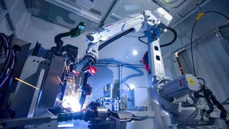
The Manipulator (Robot): Typically a 6-axis articulated arm (from brands like Fanuc, ABB, KUKA, Yaskawa) chosen for its reach, payload (torch, wire feeder, cables), and repeatability (±0.05mm or better). For large assemblies, the robot may be mounted on a linear track (7th axis) to extend its work envelope.
-
Welding Power Source & Wire Feeder: The “engine” of the process. Modern inverter-based power sources for processes like GMAW (MIG) or GTAW (TIG) offer sophisticated pulsed and synergic control modes. These are digitally integrated with the robot controller, allowing parameters (voltage, wire feed speed, pulse waveform) to be programmed as part of the robot’s path.
-
Positioner(s) and Fixturing: This is arguably the most critical element for welding CNC-machined parts. Positioners (typically 1 or 2-axis head-tailstock turn-tables or full tilt-rotate models) orient the workpiece to present joints in the optimal “flat” or “horizontal” position for welding (downhand welding). High-precision, CNC-machured fixtures—often designed and built by specialists like JLYPT—clamp the components in perfect, repeatable alignment, ensuring joint consistency across hundreds of cycles.
-
Cell Controller & Safety System: A centralized PLC coordinates all elements: initiating the robot program, indexing the positioner, controlling clamping cylinders, and managing safety devices (light curtains, area scanners, fencing). This ensures a safe, sequenced operation.
-
Peripheral Systems: Includes torch cleaning stations (reamer and cutter to remove spatter), fume extraction arms or downdraft tables, and seam tracking sensors.
1.2 Welding Processes Optimized for Robotic Cells
The choice of process depends on material, joint design, and quality requirements.
-
Robotic Gas Metal Arc Welding (GMAW/MIG): The most common process in robotic welding cells due to its speed, efficiency, and good penetration. Ideal for steel and aluminum structural fabrications. Synergic pulsed transfer modes allow for clean, spatter-free welding of thinner materials.
-
Robotic Gas Tungsten Arc Welding (GTAW/TIG): Used where exceptional weld bead aesthetics, superior metallurgical control, and high purity are required (e.g., stainless steel for food/pharma, aluminum for high-end enclosures). Slower than GMAW but offers unparalleled precision.
-
Robotic Laser Welding: Offers extremely low heat input, minimal distortion, and very high speeds. Excellent for welding thin materials, hermetic seals, and complex joints with limited access. Represents the high-end of robotic welding cell technology, requiring precise joint fit-up—a perfect match for CNC-machined components.
Table 1: Comparative Analysis of Robotic Welding Processes for CNC Machined Assemblies
| Process | Energy Source | Filler Metal | Key Advantages | Key Challenges | Ideal for CNC Machined Parts Made Of: |
|---|---|---|---|---|---|
| Robotic GMAW (MIG) | Electric Arc (Consumable Wire Electrode) | Yes, from spool | High deposition rates; deep penetration; relatively forgiving to minor fit-up variations; cost-effective. | Potential for spatter; requires post-weld cleanup; higher heat input can cause distortion. | Low-carbon & stainless steels, aluminum (with pulsed spray transfer). |
| Robotic GTAW (TIG) | Electric Arc (Non-Consumable Tungsten Electrode) | Optional (hand-fed or cold wire feed) | Excellent arc control; superior bead appearance; very clean, low-spatter welds; works on wide range of thicknesses. | Slower deposition rate; requires excellent joint fit-up and cleanliness; higher operator skill for programming. | Stainless steel, aluminum, titanium, copper alloys, and critical cosmetic welds. |
| Robotic Laser Welding | Focused Laser Beam (Fiber, Disc, CO2) | Optional (Autogenous or with wire) | Extremely fast; very low heat input & distortion; can weld dissimilar metals; high precision. | Very high equipment cost; demands exceptional joint fit-up (gap <10% material thickness); sensitive to surface condition. | Thin-gauge stainless, precision aluminum housings, hermetic titanium seals, battery tab welding. |
Section 2: The Critical Link: Designing CNC Components for Robotic Welding Cells
The manufacturability of a weldment is determined at the design stage. Components destined for robotic welding cells must be engineered with automation in mind.
Design for Welding Automation (DFWA) Principles
-
Accessibility: The joint must be physically reachable by the robotic torch at the required angle. Consider robot wrist size and torch neck length. Internal corners may require specialized torches.
-
Consistent Joint Geometry: The robot follows a programmed path. Variations in gap, mismatch, or edge preparation will result in inconsistent weld quality. CNC machining is ideal for creating precise, repeatable weld preparations (V-grooves, J-grooves, U-grooves) on mating parts.
-
Fixturing and Locating Features: Design in positive locating features—machined pads, pilot holes, or stepped registers—that allow the fixture to securely and repeatably clamp the parts without interfering with the weld path or final assembly. These features are often best added during the CNC machining process.
-
Distortion Management: Through clever design, such as using symmetrical weld joints, adding stiffening ribs before welding, or specifying machining allowances for post-weld machining, distortion can be minimized. Robotic welding cells, with their consistent heat input, make distortion more predictable and manageable.
The Fixturing Imperative
The fixture is the literal bridge between the CNC world and the welding world. A well-designed fixture for a robotic welding cell must:
-
Locate from Machined Datums: Clamp on finished surfaces or precision holes/bosses, not on as-cast or sheared edges.
-
Provide Positive Clamping: Use pneumatic or hydraulic clamps with sufficient force to resist thermal expansion during welding, but without distorting the thin-walled components.
-
Manage Heat and Spatter: Incorporate copper backer bars or chill bars behind joints to control penetration and prevent burn-through. Use anti-spatter coatings or sprays on fixture surfaces.
-
Allow for Expansion: In some cases, fixtures must allow for controlled thermal movement to prevent stress buildup during welding.
-
Facilitate Loading/Unloading: Be designed for ergonomic and efficient manual or automated part loading, often in coordination with the robot’s cycle.
Section 3: Programming, Simulation, and Process Control in Robotic Welding Cells
Programming a robotic welding cell is a specialized engineering discipline that merges robotics knowledge with deep welding process expertise.
: Offline Programming (OLP) and Digital Twin Simulation
Manually teaching a complex 3D weld path on a robot is time-consuming and takes the cell offline. OLP software (e.g., RoboDK, OCTOPUZ, or OEM-specific tools like RobotStudio for ABB) is essential.
-
Import CAD Models: The digital models of the part and fixture are imported.
-
Program Paths Offline: Weld paths are created virtually, often using the CAD model’s geometry to define seam trajectories. Welding parameters (WFS, voltage, weave patterns) are assigned to each segment.
-
Collision-Free Simulation: The software simulates the entire cycle—robot motion, positioner rotation, tooling movement—to verify no collisions occur and to optimize cycle time.
-
Generate and Download Code: The verified program is post-processed into the robot’s native language and downloaded to the cell controller. This method slashes programming time by 70% or more and is crucial for prototyping and high-mix production.
Adaptive Control and Sensing
To handle the natural micro-variations in even precision parts, advanced robotic welding cells incorporate sensing.
-
Touch Sensing: The robot uses the welding wire or a separate probe to physically touch the part at designated points before welding, updating its programmed path to account for minor part placement variations in the fixture.
-
Through-Arc Seam Tracking (TAST): By monitoring subtle changes in arc voltage or current as the torch moves, the system can detect a deviation from the joint centerline and make real-time robotic path corrections.
-
Laser Vision Seam Tracking: A laser vision camera mounted ahead of the torch scans the joint, providing a 3D profile of gap, mismatch, and joint location. This data is used to adjust both the robot path and welding parameters (wire feed speed, voltage) in real-time for optimal fill.
Table 2: Technical Specification Framework for a Precision Robotic Welding Cell
| Subsystem | Key Specification | Impact on Weld Quality & Throughput | Considerations for CNC Machined Parts |
|---|---|---|---|
| Robot Manipulator | Repeatability (±mm); Payload (kg); Reach (mm); # of Axes. | Determines positional accuracy of weld bead placement. | High repeatability (<±0.08mm) is critical for small, intricate welds on machined components. |
| Positioner | Load Capacity (kg); Tilting Range; Rotation Speed; Accuracy. | Enables optimal weld position, affecting bead profile and penetration. | Must handle weight of part + fixture. High stiffness minimizes vibration during welding. |
| Welding Power Source | Process Capability (GMAW, GTAW); Pulse Control; Synergic Lines; Digital Interface. | Controls arc stability, metal transfer mode, and heat input. | Synergic pulse settings are vital for welding thin-walled machined aluminum or stainless without burn-through. |
| Wire Feeder | Feed Speed Range; Accuracy; Push-Pull capability for aluminum. | Determines deposition rate and consistency. | Precision feeders are needed for delicate cold-wire TIG addition on small features. |
| Seam Tracking System | Type (Touch, TAST, Laser); Accuracy; Tracking Speed. | Compensates for fit-up variation, ensuring weld in joint. | Laser systems are ideal for complex 3D joints common in machined assemblies, but require excellent part preparation. |
| Fixture | Clamping Force; Locating Accuracy; Material (copper, steel); Cooling. | Ensures joint consistency and manages thermal distortion. | Must be machined to tight tolerances. Copper chill blocks are often necessary for thin sections. |
| Cell Controller | PLC brand; I/O count; Safety-rated inputs; HMI. | Coordinates all subsystems for safe, repeatable cycles. | Must interface with plant MES for job tracking and data collection on weld parameters. |
Section 4: Case Studies – Robotic Welding Cells Elevating CNC-Based Products
Case Study 1: Semiconductor Equipment – Aluminum Vacuum Chambers
-
Challenge: A manufacturer of plasma etch tools needed to weld large, complex 6061-T6 aluminum chambers. Manual TIG welding resulted in inconsistent penetration, significant distortion requiring massive post-weld re-machining, and low throughput.
-
Solution: Implementation of a dual-station robotic welding cell with a high-payload 6-axis robot on a linear track and a heavy-duty positioner. The cell was equipped with a pulsed GMAW (MIG) power source with an advanced spray transfer mode for aluminum. All chamber components were CNC machined with integral weld preparations. Custom copper-backed fixtures were designed to clamp the parts and act as heat sinks.
-
Outcome: Weld cycle time reduced by 65%. Distortion was minimized and became predictable, reducing post-weld machining allowance and saving material. Weld quality consistency achieved 100% pass rate on helium leak checks. The robotic welding cell became the bottleneck-remover for the entire chamber production line.
Case Study 2: Hydraulic Valve Manifold Blocks – Stainless Steel
-
Challenge: A fluid power company manufactured custom hydraulic manifolds by CNC milling individual channel plates from 316L stainless steel and then capping them. Manual sealing welds around the perimeter were slow and occasionally leaked under high pressure.
-
Solution: A compact, single-station robotic welding cell with a GTAW (TIG) package was deployed. The fixture was a simple but precise vise-like clamp machined from copper. The robot program was generated entirely offline from the CAD model of each unique manifold. A through-arc seam tracking system was implemented to adjust for minor plate flatness variations.
-
Outcome: Welding speed increased by 50%. The automated, precise control of the TIG arc resulted in flawless, full-penetration welds with a smooth cap, eliminating post-weld grinding and achieving a 100% seal rate on 10,000 PSI pressure tests. The cell’s flexibility allowed it to handle hundreds of different manifold designs with only a program change.
Case Study 3: Aerospace Engine Mounts – Titanium Fabrication
-
Challenge: Welding high-strength titanium (Ti-6Al-4V) engine mounting brackets required an inert atmosphere to prevent embrittlement. Manual welding in a purge box was slow, ergonomically difficult, and produced variable results.
-
Solution: A fully enclosed robotic welding cell was built with an integrated vacuum/purge system. The cell featured a robotic laser welder. The bracket components were precision CNC machined from titanium forgings, with joint gaps held under 0.1mm. A laser vision seam tracking system provided closed-loop control.
-
Outcome: The laser welding process, with its extremely low heat input, virtually eliminated distortion and preserved the base material’s metallurgical properties. The automated purge cycle ensured perfect weld purity. The cell produced X-ray and UT-quality welds at a rate three times faster than the manual method, meeting stringent aerospace certification standards consistently.
Conclusion: From Discrete Components to Integrated Systems – The Strategic Role of Robotic Welding Cells
The implementation of robotic welding cells represents a strategic maturation for manufacturers who have already mastered CNC machining. It is the logical step from producing exemplary individual components to delivering complete, welded assemblies with equal levels of quality, repeatability, and efficiency. The synergy is profound: CNC machining provides the geometrically perfect, clean components that enable robotic welding to perform at its peak potential, while robotic welding adds durable, permanent value in a controlled, automated process.
Achieving this synergy demands a holistic view. It requires designing for weldability, engineering precision fixturing, mastering offline programming and simulation, and understanding the nuances of the welding process itself. The return on investment is measured not just in labor savings, but in reduced scrap, minimized rework, faster throughput, and the attainment of weld quality levels that open doors to more demanding markets and higher-value contracts.
For companies looking to bridge the gap between their CNC machining capabilities and finished assembly, the path involves careful planning and often, the right partnership. At JLYPT, our deep experience in precision machining naturally extends into supporting our clients’ broader manufacturing goals, including the design and specification of components destined for automated assembly and welding systems.
Ready to explore how robotic welding cells can complete your precision manufacturing ecosystem? Contact JLYPT to discuss your assembly challenges and component requirements. Discover our integrated approach at JLYPT CNC Machining Services.


