Technical Drawing and CAD Modeling Services: The Foundation of Precision CNC Machining
In the world of precision manufacturing, the journey from concept to component begins not with cutting tools, but with pixels and vectors—where meticulous technical drawings and sophisticated CAD models form the essential blueprint for manufacturing excellence.
Technical drawing and CAD modeling services represent the critical first step in the digital manufacturing workflow, transforming conceptual ideas into manufacturable designs. As specialized providers of CNC machining services, we understand that the quality of manufacturing outcomes is fundamentally determined by the precision and clarity of the engineering documentation that precedes physical production. These digital foundations serve as the universal language connecting design intent with manufacturing execution, ensuring that every machined component meets exact specifications regardless of complexity.
The evolution from traditional drafting boards to sophisticated 3D CAD modeling has revolutionized how manufacturers approach component design and production. Modern CAD systems don’t merely represent geometry—they encapsulate manufacturing intelligence, material properties, functional requirements, and quality standards in a comprehensive digital package that guides every aspect of the CNC machining process.
The Critical Role of Technical Documentation in CNC Manufacturing
In precision machining, the absence of comprehensive technical documentation creates immediate challenges that compromise quality, efficiency, and cost-effectiveness. Technical drawings and CAD models serve as the contractual and technical foundation that aligns all stakeholders throughout the manufacturing process.
The Language of Manufacturing: Technical Drawing Standards
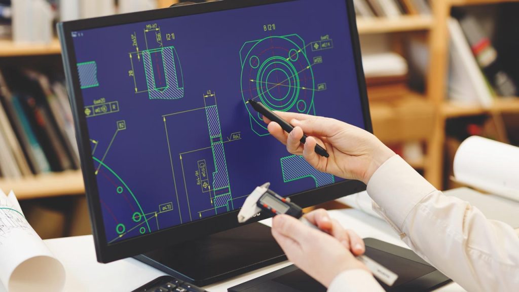
Technical drawings represent the universal language of manufacturing, communicating essential information through standardized conventions and symbols. These documents transcend linguistic barriers and provide unambiguous instructions for machinists, quality inspectors, and engineers alike.
Essential Elements of Manufacturing-Ready Technical Drawings:
-
Multiple Orthographic Views: Front, top, side, and isometric projections showing the component from all angles
-
Detailed Section Views: Cross-sectional representations revealing internal features and hidden geometries
-
Comprehensive Dimensioning: Complete size specifications with appropriate tolerances for all features
-
Geometric Dimensioning and Tolerancing (GD&T): Advanced tolerance framework controlling form, orientation, and location
-
Surface Finish Specifications: Texture requirements for functional and aesthetic surfaces
-
Material Callouts: Specific material grades, specifications, and heat treatment requirements
-
Hardware and Assembly Notes: Fastener specifications and assembly instructions
The implementation of standardized drawing practices according to ASME Y14.5 ensures consistent interpretation across manufacturing teams, supply chains, and quality assurance departments. This standardization eliminates ambiguity and reduces the risk of misinterpretation that leads to manufacturing errors.
The Digital Evolution: CAD Modeling in Modern Manufacturing
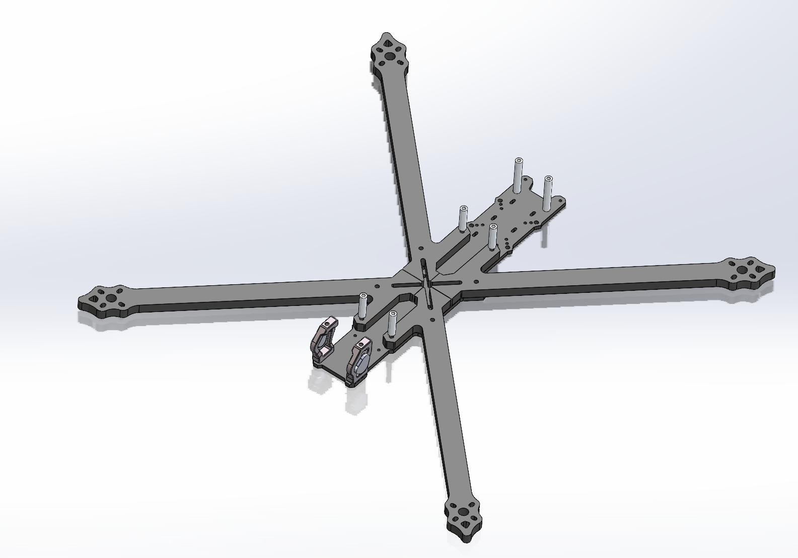
While technical drawings provide essential manufacturing information, 3D CAD models deliver a comprehensive digital representation that enables advanced manufacturing capabilities:
-
Digital Mockups: Virtual assembly and interference checking before physical production
-
CNC Programming: Direct toolpath generation from 3D geometry
-
Simulation and Analysis: Finite element analysis (FEA) and computational fluid dynamics (CFD)
-
Rapid Prototyping: Direct interface with 3D printing and additive manufacturing systems
-
Digital Inspection: Comparison of manufactured parts to original CAD data
The transition from 2D documentation to integrated 3D model-based definition (MBD) represents the current state-of-the-art in manufacturing documentation, where the 3D model contains all necessary manufacturing information without supplemental 2D drawings.
CAD Modeling Technologies and Methodologies
The selection of appropriate CAD modeling approaches significantly impacts both design efficiency and manufacturing outcomes. Different modeling methodologies offer distinct advantages for specific applications.
Parametric Modeling vs. Direct Modeling
Table 1: CAD Modeling Approaches Comparison
| Modeling Method | Definition | Best Applications | Advantages | Limitations |
|---|---|---|---|---|
| Parametric Modeling | Feature-based history with dimensional constraints | Design iterations, family of parts, engineering changes | Design intent preservation, automatic update propagation | Rigid structure, difficult legacy model editing |
| Direct Modeling | Geometry-focused manipulation without history | Conceptual design, legacy data reuse, quick modifications | Flexibility, ease of use, handling imported geometry | No design intent capture, manual updates |
| Synchronous Technology | Hybrid approach combining both methodologies | Design optimization, reverse engineering, manufacturing preparation | Flexibility of direct editing with parametric control | Steeper learning curve, specific software requirements |
| Surface Modeling | Complex organic forms using mathematical surfaces | Automotive, aerospace, consumer products aesthetics | Unlimited form freedom, Class A surfaces | Time-consuming, difficult modifications |
Industry-Standard CAD Platforms
The manufacturing industry has consolidated around several dominant CAD platforms, each with distinct strengths and specialized applications:
-
SOLIDWORKS: Comprehensive mechanical design with strong manufacturing integration
-
Autodesk Inventor: Professional-grade mechanical design and tooling
-
Siemens NX: Advanced surface modeling and aerospace applications
-
PTC Creo: Parametric modeling with strong legacy support
-
CATIA: Complex surface development for automotive and aerospace
-
Fusion 360: Cloud-based collaborative design environment
Each platform offers unique capabilities for specific manufacturing scenarios, with selection depending on component complexity, industry requirements, and integration with existing manufacturing workflows.
Technical Drawing Standards for CNC Machining
Creating manufacturing-ready technical drawings requires adherence to specific standards and practices optimized for CNC machining processes.
Tolerance Strategy and Application
The appropriate application of tolerances represents one of the most critical aspects of technical drawing creation. Proper tolerance strategy balances manufacturing cost with functional requirements:
Table 2: Tolerance Guidelines for CNC Machining Applications
| Feature Type | Standard Tolerance | Precision Tolerance | Critical Applications | Manufacturing Impact |
|---|---|---|---|---|
| Linear Dimensions | ±0.005″ (±0.127mm) | ±0.001″ (±0.025mm) | Housing fits, clearances | 15-25% cost increase for precision |
| Hole Diameters | ±0.002″ (±0.051mm) | ±0.0005″ (±0.013mm) | Bearing presses, pins | 30-50% cost increase for precision |
| True Position | Ø0.010″ (Ø0.254mm) | Ø0.002″ (Ø0.051mm) | Bolt patterns, assemblies | 40-60% cost increase for precision |
| Flatness | 0.005″ (0.127mm) | 0.001″ (0.025mm) | Sealing surfaces, mounts | 20-35% cost increase for precision |
| Surface Finish | 125 μin (3.2 μm) | 32 μin (0.8 μm) | Bearing surfaces, seals | 25-45% cost increase for precision |
Geometric Dimensioning and Tolerancing (GD&T)
GD&T provides a sophisticated framework for controlling geometric characteristics that traditional plus/minus tolerancing cannot adequately address. Key GD&T concepts for CNC machining include:
-
Datums and Reference Frames: Establishing coordinate systems for measurement and manufacturing
-
Form Controls: Straightness, flatness, circularity, and cylindricity
-
Orientation Controls: Parallelism, perpendicularity, and angularity
-
Location Controls: Position, concentricity, and symmetry
-
Profile Controls: Profile of a surface and profile of a line
Proper GD&T implementation ensures that components function as intended while maximizing the available tolerance zone and providing clear inspection criteria.
Design for Manufacturing (DFM) in CAD Modeling
The most effective CAD modeling services incorporate manufacturing considerations throughout the design process, optimizing components for CNC machining efficiency, cost-effectiveness, and quality.
CNC-Specific DFM Principles
Successful DFM for CNC machining requires attention to specific manufacturing constraints and opportunities:
-
Tool Access and Clearance: Ensuring features are accessible with standard cutting tools
-
Internal Radii Standardization: Matching corner radii to common tool sizes
-
Feature Depth Considerations: Avoiding excessively deep pockets and thin walls
-
Material-Specific Strategies: Adapting designs to material machining characteristics
-
Multi-Setup Minimization: Designing for complete machining in minimal setups
CAD Modeling Techniques for Machining Optimization
Advanced CAD modeling techniques specifically enhance manufacturability:
-
Parametric Design Tables: Creating configurable components for part families
-
Design Validation Tools: Interference detection and clearance verification
-
Manufacturing Feature Recognition: Identifying machinable features automatically
-
Model Simplification: Preparing CAD data for efficient toolpath generation
Real-World Case Studies: Technical Drawing and CAD Modeling Excellence
Case Study 1: Aerospace Component Redesign for Improved Manufacturability
An aerospace manufacturer needed to redesign a critical engine mounting bracket that consistently failed to meet quality standards despite multiple manufacturing attempts.
Challenge: Redesign a complex structural bracket with 45 individual features, tight positional tolerances, and difficult-to-machine geometries that resulted in 65% first-article rejection rate.
CAD Modeling Solution:
-
Complete Model Recreation: Parametric CAD model with proper feature history and design intent
-
DFM Analysis: Identification of problematic features including deep pockets with small corner radii
-
Tolerance Optimization: Strategic tolerance allocation based on functional requirements
-
Manufacturing Simulation: Virtual machining verification to identify access issues
Technical Drawing Enhancements:
-
Implemented ASME Y14.5-2018 GD&T standards with functional datum structure
-
Added comprehensive section views and detail callouts for complex features
-
Included surface finish symbols specific to functional interfaces
-
Provided alternative representation for repetitive pattern features
Results: The redesigned component achieved 100% first-article acceptance with a 42% reduction in machining time and 35% lower manufacturing cost. The comprehensive technical documentation eliminated interpretation errors and provided clear inspection criteria.
Case Study 2: Medical Device Assembly Documentation
A surgical instrument company required complete technical documentation for a new laparoscopic tool assembly consisting of 28 components with complex interactions.
Challenge: Create manufacturing-ready documentation for a sophisticated mechanism with tight clearances, complex kinematics, and medical-grade surface requirements.
CAD Modeling Approach:
-
Top-Down Assembly Design: Master model approach ensuring proper component interfaces
-
Interference Analysis: Comprehensive clearance checking through full range of motion
-
Tolerance Stack Analysis: Worst-case and statistical analysis of critical dimensions
-
Material Selection Integration: Medical-grade material specifications with regulatory compliance
Technical Drawing Strategy:
-
Implemented model-based definition (MBD) with 3D annotations for critical features
-
Created traditional 2D drawings for conventional machining operations
-
Developed assembly drawings with ballooned BOM and installation instructions
-
Included detailed section views of complex mechanism interactions
Results: The comprehensive documentation package enabled simultaneous component manufacturing at multiple suppliers with perfect first-time assembly. The project achieved FDA documentation requirements and reduced time to market by 35%.
Case Study 3: Industrial Equipment Legacy Component Modernization
A heavy equipment manufacturer needed to update documentation for a 25-year-old product line where original drawings were lost and replacement parts were increasingly difficult to manufacture.
Challenge: Reverse engineer and create modern CAD models and technical drawings for 15 critical components with complex geometries and no existing documentation.
Technical Documentation Process:
-
3D Scanning and Point Cloud Processing: Captured existing geometry with laser scanning
-
Parametric Model Recreation: Rebuilt components with proper design intent and feature history
-
Manufacturing Requirement Analysis: Identified critical features and functional surfaces
-
Contemporary Standard Implementation: Applied current ASME and ISO drawing standards
CAD Modeling Innovations:
-
Created configurable models allowing for future design variations
-
Implemented design for additive manufacturing where appropriate
-
Developed digital twin for future maintenance and service requirements
-
Established revision control and documentation management system
Results: The modernized documentation enabled reliable component reproduction with 100% interchangeability. Manufacturing costs decreased by 28% through design optimization and clear documentation. The digital asset management system provided foundation for future product improvements.
Advanced CAD Modeling Techniques for CNC Manufacturing
Beyond fundamental modeling, several advanced techniques significantly enhance manufacturing outcomes.
Multi-Body Modeling and In-Context Design
Sophisticated assembly modeling approaches improve design efficiency and accuracy:
-
Skeletal Modeling: Master sketch technique controlling multiple components
-
Layout-Based Design: 2D layout driving 3D component geometry
-
In-Context References: Cross-part relationships maintaining design intent
-
Derived Component Patterns: Associative feature patterns across assemblies
Surface Modeling for Complex Geometries
Advanced surface modeling techniques address challenges beyond basic solid modeling:
-
Boundary Surfaces: Complex forms defined by multiple guiding curves
-
Style and Freeform: Organic shapes with direct manipulation controls
-
Continuity Management: G0, G1, G2, and G3 surface transitions
-
Surface Analysis: Curvature comb, zebra stripe, and draft analysis
Model Preparation for CAM Processing
Optimizing CAD models for efficient toolpath generation requires specific techniques:
-
Model Simplification: Removing unnecessary features for machining
-
Surface Repair: Healing imported geometry with gaps and errors
-
Feature Recognition: Identifying machinable features automatically
-
Stock Model Creation: Defining raw material geometry for toolpath verification
Quality Assurance in Technical Documentation
The accuracy and completeness of technical documentation directly impacts manufacturing quality and efficiency.
Drawing Checking and Verification Processes
Systematic verification ensures documentation quality:
-
Peer Review: Cross-checking by second engineer
-
Manufacturing Review: Machinist feedback on manufacturability
-
Tolerance Analysis: Verification of tolerance stacks and fits
-
Standards Compliance: Adherence to company and industry standards
Revision Control and Documentation Management
Effective documentation management prevents errors and confusion:
-
Revision Control: Systematic tracking of documentation changes
-
Release Procedures: Controlled documentation issuance
-
Obsolete Drawing Management: Proper retirement of superseded documents
-
Digital Archive: Secure storage and retrieval of documentation history
The Future of Technical Documentation in Manufacturing
Emerging technologies continue to transform how manufacturing information is created, managed, and utilized.
Model-Based Enterprise (MBE) and Digital Thread
The transition from drawing-based to model-based manufacturing information flow:
-
3D Model-Based Definition: Incorporating all manufacturing information in 3D models
-
Digital Product Definition: Comprehensive digital product specification
-
Manufacturing Process Integration: Direct CAD-CAM-CMM data continuity
-
Supply Chain Collaboration: Extended enterprise data sharing
Artificial Intelligence in CAD Modeling
AI technologies are beginning to transform design and documentation processes:
-
Generative Design: AI-driven design exploration and optimization
-
Automated Drafting: AI-assisted drawing creation and annotation
-
Design Validation: Automated checking of standards compliance
-
Manufacturability Analysis: AI-powered DFM recommendations
Conclusion
Technical drawing and CAD modeling services form the essential foundation for successful CNC machining projects, bridging the gap between design concept and manufactured reality. The precision, clarity, and completeness of engineering documentation directly determine manufacturing efficiency, cost effectiveness, and final product quality. In an increasingly digital manufacturing landscape, these services have evolved from simple geometry representation to comprehensive digital product definition that guides every aspect of the manufacturing process.
The most successful manufacturing partnerships recognize technical documentation not as an administrative requirement, but as a strategic investment that prevents errors, reduces costs, and accelerates time to market. By implementing robust CAD modeling practices, adhering to industry standards, and incorporating manufacturing intelligence throughout the design process, organizations achieve manufacturing outcomes that consistently meet or exceed expectations.
For components requiring precision manufacturing, our integrated CNC machining services combined with professional technical documentation capabilities provide complete solutions from digital concept to physical component. Contact our engineering team to discuss how our technical drawing and CAD modeling expertise can optimize your next manufacturing project
