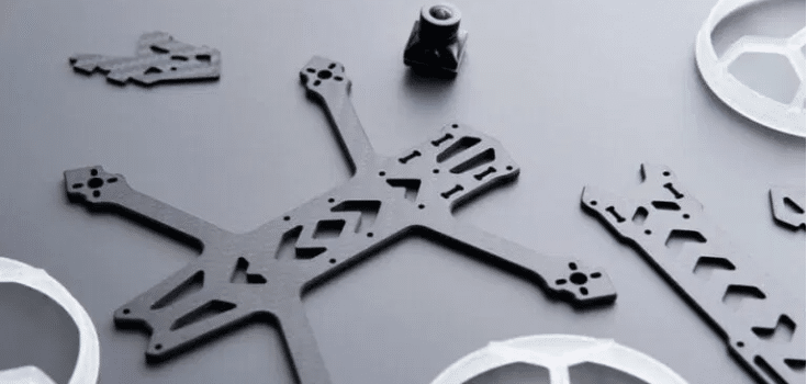
Precision Drone Parts Manufacturing: A CNC Machining Playbook for Flight-Ready Hardware (JLYPT)
Precision in drones is not an aesthetic preference, it is an engineering requirement that shows up as stable flight control, lower vibration, repeatable payload alignment, longer bearing life, and fewer “it flew fine yesterday” failures. When a multirotor starts shedding fasteners, a gimbal drifts out of calibration, or a motor develops unexplained heat, the root cause is frequently manufacturing variation hiding inside nominally identical parts.
That is why precision drone parts manufacturing is best treated as a system: CAD intent → datum strategy → CNC process planning → surface treatment allowances → inspection control plan → feedback loop to design.
This article is written for engineers, procurement teams, and UAV product owners who want a practical, shop-floor-informed view of what makes CNC-machined drone components consistent from prototype to production. You’ll find process guidance, tolerance logic, material choices, detailed tables, and three build-style case studies that reflect the real constraints of UAV programs.
If you want to go straight to a capability overview and inquiry path, include this internal link in your content plan:
Custom CNC UAV Parts Manufacturer
Table of Contents
- What “Precision Drone Parts Manufacturing” Actually Means
- Why CNC Machining Is a Core Technology for Drones
- Drone Parts That Benefit Most from Precision CNC Machining
- Material Selection for Precision Drone Parts Manufacturing
- CNC Process Stack: Milling, Turning, 5-Axis, and Mill-Turn
- Datum Design & GD&T for Drones: How to Control Vibration and Alignment
- Thin Walls, Lightweighting, and Distortion Control
- Threads, Inserts, and Fastener Interfaces That Don’t Loosen
- Surface Finishing: Anodize, Hard Anodize, Chem Film, and Nickel
- Inspection Planning: CMM Strategy, Gaging, and First Article Inspection
- Production Readiness: Process Capability, Traceability, and Lot Consistency
- Cost Drivers and DFM for CNC Drone Parts
- Three Case Studies in Precision Drone Parts Manufacturing
- External References + Internal Links
- FAQ
1) What “Precision Drone Parts Manufacturing” Actually Means
In the drone industry, “precision” is often reduced to a number like ±0.01 mm. That’s incomplete. Precision drone parts manufacturing is the disciplined ability to repeatedly hit functional requirements, the features that control:
- motor thrust axis and propeller plane alignment
- bearing seat geometry (fit, coaxiality, and surface finish)
- structural stiffness and resonance behavior
- payload boresight and gimbal reference planes
- sealing performance for enclosures exposed to dust/water
- assembly repeatability after service cycles
Precision is also about variation management: two parts can meet print and still behave differently in flight if the datum strategy, finishing allowances, or assembly interfaces are inconsistent.
Precision is “design intent preserved through manufacturing”
A practical definition you can use internally:
Precision drone parts manufacturing is the repeatable conversion of design intent into hardware through stable datums, controlled machining processes, finish-aware tolerancing, and inspection aligned to functional interfaces.
That is the benchmark you should use when evaluating any CNC supplier for drone hardware.
2) Why CNC Machining Is a Core Technology for Drones
Drones are a hybrid of aerospace and consumer electronics. They combine vibration, cyclic loads, lightweight structures, and modular assemblies, yet they also demand fast iteration cycles. CNC machining remains central because it provides:
- high stiffness materials (aluminum, titanium, stainless, alloy steels)
- controlled fits for bearings, shafts, and pilots
- complex geometry with tight positional relationships
- consistent surface finishes and edge conditions
- scalable repeatability from prototypes to low/medium volume production
Table 1 , Manufacturing Methods in Drones: Where CNC Is the Best Fit
| Manufacturing method | Typical drone use | Strengths | Typical limitations | Why CNC machining stays essential |
|---|---|---|---|---|
| CNC machining | mounts, frames, hubs, enclosures | tight tolerances, real metals, repeatability | cost per unit higher than molding at very high volume | controls datums, fits, runout, sealing glands |
| Composite layup | arms, plates, shells | high stiffness-to-weight | anisotropy, insert challenges | CNC makes the precision interfaces that composites cannot |
| Injection molding | covers, cosmetic shells | low cost at volume | tooling lead time; limited tolerance | CNC used for structural and alignment-critical parts |
| Sheet metal | brackets, guards | quick and affordable | limited 3D stiffness, fewer precision interfaces | CNC required for bearing seats and pilots |
| Additive manufacturing | ducts, brackets, prototypes | fast complex shapes | tolerance, finish, anisotropy | CNC finishing often needed for critical features |
In short, precision drone parts manufacturing uses CNC machining to ensure interfaces remain consistent when the airframe is vibrating and the control loops are demanding stable signals.
3) Drone Parts That Benefit Most from Precision CNC Machining
Not every drone component requires the same level of control. The highest ROI on precision is typically found where misalignment creates vibration, heat, or calibration drift.
Table 2 , Drone Component Map for Precision CNC Machining
| Component | Primary function | Typical CNC process | Why precision matters | Key controlled features |
|---|---|---|---|---|
| Motor mount | align motor + distribute thrust | CNC milling / 5-axis | tilt causes vibration + control noise | flatness, perpendicularity to pilot, bolt circle true position |
| Hub adapter | prop interface | CNC turning / mill-turn | runout increases vibration | concentricity, circular runout, face runout |
| Bearing housing | support rotating shaft | CNC turning / milling | poor fits reduce bearing life | seat diameter, finish Ra, coaxiality |
| Arm clamp / joints | structural connection | CNC milling | micro-slip loosens fasteners | parallelism, clamp symmetry, radii |
| Payload bracket | sensor alignment | 5-axis milling | boresight shifts degrade data | datum planes, hole true position |
| Avionics enclosure | protect electronics | CNC milling | sealing + EMI needs | O-ring gland geometry, flatness |
| Thermal plate / ESC tray | heat management | CNC milling | uneven contact raises temps | flatness, surface finish |
| Landing gear joints | impact load | CNC milling | fatigue can initiate at edges | fillets, edge break, finish quality |
A good rule: if a feature controls an axis (motor axis, prop axis, gimbal axis), treat it as a precision feature with a deliberate datum chain and inspection plan.
4) Material Selection for Precision Drone Parts Manufacturing
Material choice is where cost, stiffness, fatigue, corrosion, and finishing constraints converge. In precision drone parts manufacturing, the “best” material is the one that meets the mechanical need while remaining stable and predictable through machining and finishing.
Table 3 , Common CNC Materials for Drone Components (Engineering View)
| Material | Typical drone use | Why it’s used | Watch-outs | Practical notes for CNC machining |
|---|---|---|---|---|
| 6061-T6 aluminum | brackets, trays, enclosures | great machinability, corrosion resistance | lower strength than 7075 | excellent for prototypes and general structures |
| 7075-T6 aluminum | arms, clamps, load nodes | high strength-to-weight | more notch sensitive; corrosion | often paired with Type III hard anodize |
| 6082 aluminum | structural EU preference | good strength + corrosion | availability varies | similar strategy to 6061 in many builds |
| Ti-6Al-4V | high-load, weight-critical joints | exceptional strength-to-weight | machining time + tool wear | plan conservative feeds; manage heat |
| 17-4PH stainless | hubs, shafts, couplers | strong + corrosion resistant | distortion with heat treatment | consider finish machining after heat treat |
| 304/316 stainless | wet/chemical environments | corrosion resistance | lower strength; gummy | better for brackets than highly loaded nodes |
| 4140 alloy steel | drive components | fatigue strength | heavy; corrosion | protective finishes often required |
| POM (Delrin) | spacers, insulators | low friction, stable | lower stiffness | great for non-structural precision spacers |
| PEEK | high-temp insulators | high performance | expensive | use where temperature/chem resistance matters |
Material + finish must be planned together
A frequent failure mode in drone hardware is designing a fit (like a pilot diameter or bearing seat) without accounting for the coating thickness and growth behavior. Precision drone parts manufacturing treats coating as part of the dimensioning strategy, not an afterthought.
5) CNC Process Stack: Milling, Turning, 5-Axis, and Mill-Turn
Drone parts often look simple until you try to preserve alignment across multiple faces or maintain stiffness while aggressively lightweighting.
5.1 CNC Milling (3-Axis, 3+2, and 5-Axis)
- 3-axis milling is efficient for plates, pockets, and simple brackets.
- 3+2 (positional 5-axis) reduces setup count for multi-face parts.
- Full 5-axis enables tool access for deep pockets, compound angles, and contoured structures, often with better surface finish and less setup error.
Table 4 , Choosing 3-Axis vs 5-Axis in Precision Drone Parts Manufacturing
| Part geometry | Best-fit process | Why | Benefit |
|---|---|---|---|
| Flat tray with pockets | 3-axis | simplest fixturing | lowest cost |
| Multi-face bracket with angled planes | 3+2 | fewer setups | improved positional accuracy |
| Frame node with compound angles | 5-axis | maintains datum relationships | reduces stack-up error |
| Lightweight part with deep ribs | 5-axis | better tool engagement | less chatter, better finish |
5.2 CNC Turning and Mill-Turn for Propulsion Interfaces
Turning is the backbone for concentric features: bores, pilots, bearing seats, and shafts. Mill-turn is ideal when you need turned coaxial geometry plus milled bolt circles, flats, or keyways without losing alignment.
Table 5 , Turning Features That Directly Affect Drone Vibration
| Feature | Why it matters | Preferred manufacturing approach |
|---|---|---|
| Concentric bore-to-OD | reduces imbalance | single-setup turning with stable chucking |
| Face runout | controls prop wobble | finish face + pilot in same setup |
| Bearing seat finish | reduces fretting | controlled feed; optional polishing |
| Thread quality | prevents loosening | correct class; gauge verification |
Precision drone parts manufacturing is often won or lost on rotating interfaces, small geometric errors can become large vibration forces at RPM.
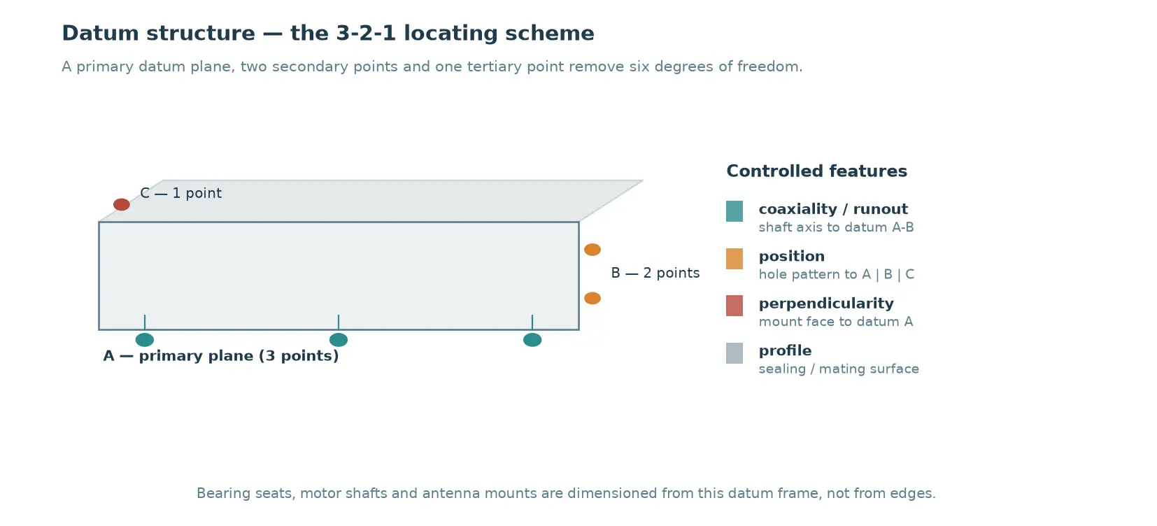
6) Datum Design & GD&T for Drones: How to Control Vibration and Alignment
If your drawings don’t define functional datums, the shop will be forced to guess what matters. That guess becomes variation.
6.1 Datums that match real drone physics
Practical datum suggestions:
- Motor mount: pilot axis as primary datum; mounting face as secondary
- Hub adapter: bore axis primary; prop seating face secondary
- Enclosure: sealing plane primary; connector cutouts referenced to it
- Payload mount: sensor datum plane primary; dowel/locators secondary
6.2 GD&T that improves flight behavior
In precision drone parts manufacturing, GD&T is used to control relationships, not just size.
Table 6 , High-Value GD&T Callouts for Drone CNC Parts
| Component | Recommended GD&T | What it protects |
|---|---|---|
| Motor mount | perpendicularity (face to pilot axis) | thrust-axis alignment |
| Motor mount | true position (bolt circle to pilot) | assembly repeatability |
| Hub adapter | circular runout (face to bore axis) | vibration reduction |
| Bearing housing | coaxiality / position | bearing life and efficiency |
| Payload bracket | flatness + true position | boresight repeatability |
| Enclosure | profile / flatness of sealing surface | IP sealing integrity |
6.3 Tolerancing without over-paying
Not every surface needs aerospace tolerances. The strategy is to tighten only what controls alignment, load transfer, sealing, and rotating performance.
Table 7 , Practical Tolerance Targets (Typical Starting Points)
| Feature | Typical target (example) | Why |
|---|---|---|
| Motor pilot diameter | ±0.01–0.02 mm | controls centering |
| Mounting face flatness | 0.02–0.05 mm | avoids tilt |
| Bolt circle true position | 0.05–0.10 mm | avoids assembly stress |
| Bearing seat diameter | fit-driven (H7 style concept) | controls preload and creep |
| Cosmetic outer surfaces | ±0.20–0.50 mm | cost control |
A competent supplier will ask which features are “flight-critical” and build the machining/inspection plan around them, this is central to precision drone parts manufacturing.
7) Thin Walls, Lightweighting, and Distortion Control
Lightweighting is not just pocketing material. It is managing stiffness, resonance, and machining stability.
7.1 Common distortion sources in drone parts
- aggressive pocketing on one side only (unbalanced stress relief)
- thin wall sections without intermediate supports
- long-reach tooling causing chatter and heat
- finishing after anodize without controlling growth
- multiple setups without a stable datum transfer plan
7.2 CNC strategies that reduce warp
- roughing in stages and leaving uniform stock for finishing
- symmetric material removal when possible
- finish critical faces last
- use dedicated soft jaws / vacuum fixtures / custom nest fixtures
- avoid unnecessarily thin ribs; add radii to lower stress concentration
Table 8 , Lightweight Design Choices vs Manufacturing Risk
| Lightweight feature | Performance benefit | Manufacturing risk | Mitigation in CNC process |
|---|---|---|---|
| deep pockets | mass reduction | wall flex + chatter | 5-axis access, step-down strategy |
| thin ribs | stiffness per gram | distortion after unclamp | leave stock, finish in final setup |
| lattice-like pattern | resonance tuning | tool access limitations | larger tool radii, 5-axis approach |
| sharp internal corners | packaging | fatigue crack initiation | add fillets, use proper endmill radius |
Precision drone parts manufacturing is as much about controlling shape stability as it is about holding dimensions.
8) Threads, Inserts, and Fastener Interfaces That Don’t Loosen
Field serviceability is a hidden requirement in drones. Parts that are removed for transport or repaired in the field must survive repeated torque cycles.
8.1 Thread selection and engagement depth
- Choose thread sizes that match load and available wall thickness.
- Avoid marginal engagement in soft aluminum for high-cycle joints.
- Consider stainless inserts or helicoils where torque repeatability is essential.
8.2 Practical anti-loosening design (without “over-torquing”)
- use proper clamp length and surface contact
- avoid stacking soft materials under fasteners
- ensure burr-free countersinks/counterbores so torque translates to clamp load
- apply consistent surface finishing and cleanliness requirements
Table 9 , Thread/Insert Options in Precision Drone Parts Manufacturing
| Option | Best use | Pros | Cons |
|---|---|---|---|
| Direct tap in aluminum | light loads, low cycles | simplest, low cost | threads wear; torque variability |
| Helicoil | repeated service | strong threads in aluminum | installation process control needed |
| Solid threaded insert | high load + frequent service | robust | requires more wall thickness |
| Thread-forming screws | plastics, some aluminum | fast assembly | not ideal for precision assemblies |
9) Surface Finishing: Anodize, Hard Anodize, Chem Film, and Nickel
Finishes affect corrosion, wear, conductivity, and, critically, dimensions.
9.1 Anodize allowances and dimensional planning
Anodize is not “paint.” It changes effective size. For precision features:
- specify masking where needed
- define post-finish critical dimensions when appropriate
- avoid coating inside tight bearing seats unless designed for it
Table 10 , Finish Selection for Drone CNC Parts
| Finish | Typical use | Advantages | Precision cautions |
|---|---|---|---|
| Type II anodize | cosmetic + corrosion | color options, good protection | thickness affects fits slightly |
| Type III hard anodize | clamps, wear points | wear resistance | dimensional growth; mask critical fits |
| Conversion coating | electrical grounding | conductivity + corrosion | less wear protection |
| Electroless nickel | wear + uniform thickness | uniform coverage | buildup impacts tight fits |
| Passivation (stainless) | corrosion resistance | improves stability | not a wear coating |
Precision drone parts manufacturing requires finish-aware drawings; otherwise, assemblies become “select-fit by luck.”
10) Inspection Planning: CMM Strategy, Gaging, and First Article Inspection
Inspection is where you convert “we think it’s right” into evidence.
10.1 What to inspect (and how often)
A strong quality plan separates:
- critical characteristics (100% or high-frequency checks)
- key characteristics (sampling with control charts)
- non-critical (audit checks)
Table 11 , Example Inspection Plan (Motor Mount + Hub Interface)
| Characteristic | Tool | Frequency | Why it matters |
|---|---|---|---|
| pilot diameter | bore gauge / CMM | 100% | centering |
| mounting face flatness | CMM / surface plate | per lot or 100% | vibration |
| bolt circle true position | CMM | sampling | assembly repeatability |
| thread go/no-go | thread gauges | 100% | torque reliability |
| coating thickness | thickness gauge | per lot | post-finish fit |
10.2 First Article Inspection (FAI) as a process validation
FAI should validate:
- the datum scheme is manufacturable
- the fixture strategy holds geometry without distortion
- finish does not break fits
- assembly is smooth without forced alignment
This is not bureaucracy, FAI is a core element of precision drone parts manufacturing when you expect repeatability across lots.
11) Production Readiness: Process Capability, Traceability, and Lot Consistency
Many drone teams can get a beautiful prototype. The harder job is producing the same part again and again.
11.1 Process capability thinking (without overcomplicating)
For critical dimensions, you want stable processes:
- consistent tool life management
- controlled workholding
- stable finishing routes
- documented inspection methods
11.2 Traceability: what matters for drone programs
Even if you’re not building full aerospace documentation, practical traceability helps when failures occur:
- material certs per lot
- revision control
- inspection records for critical features
- coating batch info
Table 12 , “Right-Sized” Documentation for Precision Drone Parts Manufacturing
| Document / record | When it’s valuable | What it prevents |
|---|---|---|
| material certification | structural parts | unknown alloy/temper issues |
| FAI report | new revision or new setup | hidden process changes |
| CMM report | GD&T-critical parts | silent drift |
| coating batch record | anodized/hard anodized parts | fit change across lots |
| packing/handling standard | cosmetic or sealing parts | dents, edge damage, contamination |
12) Cost Drivers and DFM for CNC Drone Parts
If you want better pricing and better quality, the fastest path is a manufacturing-aware design.
12.1 Major CNC cost drivers in drone components
- too many setups due to unclear datums
- deep, narrow pockets requiring long tools
- ultra-tight tolerances on non-critical geometry
- difficult finishing/masking requirements not documented
- sharp internal corners requiring small tools (time-consuming)
Table 13 , DFM Actions That Reduce Cost While Protecting Performance
| DFM change | Why it reduces cost | Performance impact |
|---|---|---|
| loosen non-critical tolerances | less cycle time + inspection | none if chosen correctly |
| add internal radii | allows larger tools | improves fatigue life |
| reduce setup count via datum redesign | less stack-up + less time | improves repeatability |
| standardize fasteners | simplifies machining + assembly | improves serviceability |
| design finish allowances | avoids rework after anodize | improves assembly yield |
Precision drone parts manufacturing is not “make everything tighter.” It is “make the right things controlled.”
13) Three Requirement Profiles in Precision Drone Parts Manufacturing
The following cases reflect common drone manufacturing challenges and the CNC process choices that typically solve them. Specific dimensions and customer identifiers are omitted; the engineering logic is the point.
ExampleA , Low-Vibration Motor Mount + Hub Adapter Set (Runout and Datum Control)
Goal: reduce vibration and stabilize flight-control sensor readings at mid-to-high RPM.
Key issues observed in the field
- prop plane wobble after replacement parts installed
- inconsistent torque feel due to burrs and coated threads
- motor tilt due to mount face variation
Precision drone parts manufacturing approach
- Turn hub pilot + seating face in a single setup to preserve coaxiality.
- If bolt pattern milling is needed, use datum-preserving fixturing (or mill-turn) so the bolt circle is located from the same axis used in turning.
- Mill motor mount with pilot axis and mounting face defined as functional datums; finish these faces late in the process.
- Add controlled edge break and strict deburring around bolt holes and tapped holes to stabilize torque-to-clamp-load behavior.
- Verify circular runout and face runout for the hub adapter, plus perpendicularity for the motor mount.
Result (typical)
- reduced vibration-related tuning time
- more consistent “swap-and-fly” behavior for spare parts
- fewer complaints of unexplained noise bands at certain RPM ranges
ExampleB , Sealed Avionics Enclosure (O-Ring Gland Accuracy + Flatness)
Goal: a CNC-machined electronics enclosure that maintains sealing integrity while staying serviceable.
Key manufacturing risks
- O-ring gland geometry out of spec (seal compression wrong)
- warped sealing surfaces after machining or finishing
- inconsistent surface finish causing micro-leaks
- coating thickness interfering with cover fit
Precision drone parts manufacturing approach
- Define sealing plane as primary datum; reference all groove geometry and cover holes to it.
- Machine the O-ring gland with toolpaths that maintain consistent groove width/radius; avoid chatter marks.
- Control flatness on the sealing land; keep Ra appropriate for sealing.
- Plan coating with clear masking notes on sealing lands if needed.
- CMM inspection for groove geometry and flatness, plus fit-check with production hardware.
Result (typical)
- fewer field returns for “mysterious moisture” issues
- faster assembly with predictable gasket compression
- improved reusability after maintenance cycles
ExampleC , Lightweight 7075 Frame Node (5-Axis Access + Distortion Management)
Goal: a structural node with deep pockets and angled interfaces that must stay stable under thrust loads.
Key challenges
- thin walls distort after unclamping
- multiple setups create positional stack-up
- anodize changes mating fits
Precision drone parts manufacturing approach
- Use 5-axis machining to reduce setups and preserve datum relationships across faces.
- Rough in stages to relieve internal stresses gradually; leave uniform stock for finishing.
- Finish critical mating faces late; keep balanced material removal where possible.
- Specify finish allowance and mask the most sensitive mating pilots if required.
- Inspect key interfaces with CMM to confirm true position across angled planes.
Result (typical)
- better assembly alignment without forced fasteners
- reduced scrap from warp-related out-of-tolerance conditions
- more stable flight feel due to consistent stiffness and geometry
14) External References + Internal Links
Internal links (recommended placement within your blog)
- Core service page: Custom CNC UAV Parts Manufacturer
- Homepage (brand/entity strengthening): JLYPT
External references
- International standards directory (useful for GD&T and manufacturing standards context): ISO standards
- Materials and test standards library (useful for alloy and coating references): ASTM standards
- Measurement and metrology resources: NIST
(These references are general background. Your drawings, specifications, and acceptance criteria should define the exact requirements for your drone components.)
15) Conclusion: Building Repeatability Into Precision Drone Parts Manufacturing
The fastest way to improve drone reliability is not chasing extreme tolerances everywhere, it’s building a manufacturing system that protects the features that drive flight behavior: alignment, runout, sealing, stiffness, and serviceability. When datums are clear, machining is setup-efficient, finishes are planned, and inspection is functional, the parts stop being “good enough” and become repeatable.
If your team is sourcing or upgrading a supply chain for precision drone parts manufacturing, JLYPT supports CNC process planning and production workflows aimed at stable, flight-ready output. Start here:
Custom CNC UAV Parts Manufacturer
FAQ
What’s the biggest cause of vibration in machined drone parts?
Most often: runout/concentricity errors in hub interfaces, motor mount perpendicularity issues, and assembly variation caused by burrs or inconsistent contact surfaces. Precision drone parts manufacturing prioritizes these interfaces in both process planning and inspection.
How do you prevent anodize from breaking fits?
You plan it early: define which surfaces must be masked, apply finish allowances to pilots and bores, and verify coating thickness per lot. Treat coating as part of the dimensional stack.
When should I choose 5-axis machining for drone parts?
When you need multi-face positional accuracy, compound angles, deep pockets with better tool access, or you want to reduce setup count to control stack-up errors, common in lightweight structural nodes and payload brackets.
Four inputs decide most quotes: the drawing, the material grade, which features carry tolerance, and target quantity. Put those through the JLYPT quote form and pricing comes back tied to them, with wall thickness below 1 mm priced in rather than averaged. The production setup behind it is described on the UAV machining cell.