
Aerospace CNC Machining Services: A Practical Engineering Guide to Flight-Grade CNC Manufacturing (JLYPT)
Aerospace parts do not fail politely. When a bracket cracks, a bore drifts, or a sealing land warps, the consequence is rarely limited to scrap and rework—it can become downtime, grounding events, or systemic reliability issues. That’s why Aerospace CNC machining services are fundamentally different from generic CNC work: success is measured not only by dimensional conformance, but also by traceability, process repeatability, surface integrity, and inspection evidence that stands up to audits and long service cycles.
This article is built as a shop-floor-to-engineering bridge. It explains how aerospace components are planned, machined, inspected, documented, and scaled—using CNC-machining terminology and real manufacturing logic (datums, setups, toolpaths, burr control, metrology, and special-process coordination). You’ll also find multiple detailed tables you can use as checklists and three case studies that reflect common aerospace manufacturing realities.
If your program includes UAV hardware, you can also reference JLYPT’s UAV-oriented capability page here (internal link requested):
https://www.jlypt.com/custom-cnc-uav-parts-manufacturer/
Table of Contents
- What “Aerospace CNC Machining Services” Should Include
- Why Aerospace Machining Is Different (Beyond Tight Tolerances)
- Aerospace Part Families: What CNC Is Best At
- Core CNC Processes: Milling, Turning, 5-Axis, and Mill-Turn
- Material Selection and Machinability (Al, Ti, Stainless, Superalloys)
- Datum Strategy & GD&T: How to Protect Functional Geometry
- Process Planning: Setups, Workholding, Probing, and Toolpath Strategy
- Thin Walls, Distortion, and Residual Stress Management
- Burr Control, Edge Break Standards, and Surface Integrity
- Finishing and Special Processes: Anodize, Chem Film, Passivation, Plating
- Quality Evidence: AS9102 FAI, CMM Reports, Traceability, and Control Plans
- Inspection & Metrology in Aerospace CNC Machining Services
- DFM and Cost Drivers (Without Sacrificing Performance)
- Supplier Evaluation Checklist for Aerospace CNC Machining Services
- Three Case Studies (Prototype → Production Reality)
- Internal + External Links (SEO)
- Final Notes and Next Steps
1) What “Aerospace CNC Machining Services” Should Include
A buyer might treat Aerospace CNC machining services as “someone who can hold ±0.01 mm.” In practice, aerospace-ready service is a package of capabilities and behaviors, including:
- Manufacturing engineering: a documented process plan with stable datums and minimized setup stack-up
- Controlled machining: repeatable toolpaths, tool-life strategy, in-process probing when appropriate
- Surface integrity: burr control, edge conditioning, controlled surface finish, and avoidance of damage (FOD mindset)
- Inspection evidence: CMM strategy, functional gaging, and records suitable for customer review
- Traceability: material certifications, lot control, revision control, and identification methods
- Finishing coordination: coatings, heat treat, and masking requirements integrated into tolerancing and fits
- Risk management: first article validation, corrective actions, and controlled deviations if needed
Table 1 — Minimum Deliverables You Should Expect
| Deliverable | What it is | Why it matters in Aerospace CNC machining services | When it’s critical |
|---|---|---|---|
| Certificate of Conformance (CoC) | Statement the parts meet requirements | Creates accountability and release record | Every shipment |
| Material certificate / mill cert | Chemistry + mechanical properties by lot | Prevents unknown material substitutions | Structural/load parts |
| Inspection report | Dimensional results and methods | Evidence of compliance | Tight GD&T, critical features |
| AS9102 FAI package (when requested) | Formal first-article form set | Validates process and drawing interpretation | New parts, rev changes |
| CMM report (if applicable) | Measured geometry outputs | Verifies true position, profile, runout, etc. | Complex GD&T |
| Special process certs (if applicable) | For finishing/heat treat | Aerospace compliance and consistency | Coated or heat treated parts |
| Nonconformance process | MRB-like handling | Prevents silent escapes | Any deviation scenario |
If a supplier offers “tight tolerance machining” but cannot consistently provide the above, you’re not getting full Aerospace CNC machining services—you’re getting machining with hope.
2) Why Aerospace Machining Is Different (Beyond Tight Tolerances)
Aerospace hardware is engineered around predictable behavior across time: vibration, thermal cycles, corrosion exposure, load spectra, and maintenance events. The manufacturing system has to preserve design intent across all of that.
Key differentiators:
-
Functional datums dominate
Cosmetic surfaces matter less than the surfaces that locate parts in assembly and carry load. -
Tolerance is relationship-based
Positional relationships (true position, profile, runout, perpendicularity) are often more important than size alone. -
Surface integrity affects fatigue life
Burrs, sharp edges, chatter marks, and tool witness lines can become crack initiation sites. -
Documentation is part of the product
For many aerospace programs, the “deliverable” includes inspection evidence, traceability, and stable revision control. -
Finishing changes geometry
Coating thickness and growth must be designed into fits and sealing features.
This is the mindset that separates general job-shop output from Aerospace CNC machining services.
3) Aerospace Part Families: What CNC Is Best At
CNC machining is most valuable when parts require controlled interfaces, stable geometry, and reliable repeatability—especially when castings, moldings, or additive processes still require precision finishing.
Table 2 — Typical Aerospace CNC Parts and What Drives the Process Choice
| Part family | Examples | Primary CNC value | Typical risk | Typical mitigation |
|---|---|---|---|---|
| Structural brackets & fittings | ribs, lugs, clevises | strength + tight datum control | fatigue at corners | fillets, edge break, finish control |
| Housings & enclosures | avionics boxes, sensor housings | sealing and alignment | warp/thin walls | staged roughing, fixture support |
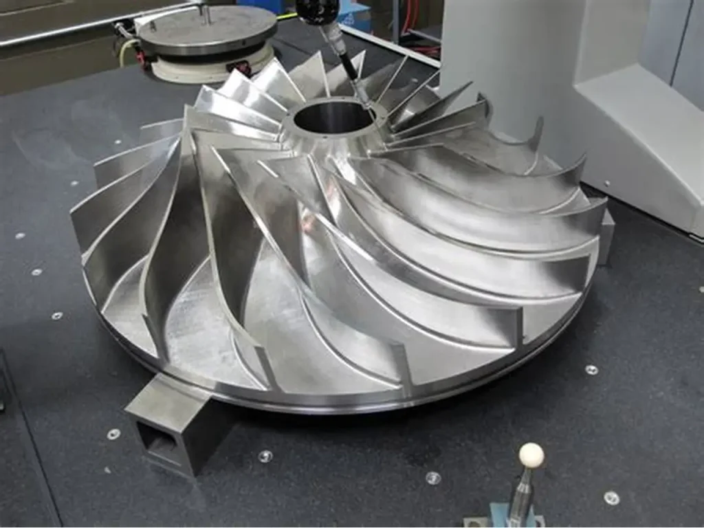
| Rotating/axisymmetric parts | spacers, hubs, sleeves | coaxiality and runout control | vibration, bearing wear | single-setup turning, gage strategy |
| Manifolds & fluid blocks | ports, galleries | leak-free geometry | burrs in passages | deburr validation, cleaning process |
| Precision interfaces | dowel patterns, pilots | assembly repeatability | stack-up error | datum strategy, setup reduction |
| UAV/aerospace hybrid parts | mounts, nodes, adapters | lightweight + stiffness | distortion | 5-axis, balanced machining |
4) Core CNC Processes in Aerospace CNC Machining Services
Aerospace programs rarely use a single process. They use a controlled mix—selected to minimize setups, protect datums, and preserve geometry.
4.1 CNC Milling (3-Axis, 3+2, and 5-Axis)
- 3-axis: efficient for plates, pockets, and straightforward brackets
- 3+2 positional: reduces setups for multi-face components while keeping programming manageable
- 5-axis simultaneous: best for contoured profiles, deep pockets with short tools, and complex compound angles
4.2 CNC Turning and Mill-Turn
Turning is essential for features like bearing seats, pilots, coaxial bores, and precision faces. Mill-turn (multi-task) adds milled features without losing concentricity—often reducing error from re-chucking.
Table 3 — Process Selection Matrix (Practical)
| Requirement | Best-fit process | Why it’s preferred in Aerospace CNC machining services | Typical inspection focus |
|---|---|---|---|
| Multi-face positional accuracy | 3+2 or 5-axis milling | fewer setups, less stack-up | true position, profile |
| Coaxial bores + milled flats | mill-turn | preserves axis in one clamping | runout, coaxiality |
| Tight bore geometry | turning + boring | best control of cylindricity | bore size, cylindricity |
| Large flat sealing land | milling + finishing pass | controls flatness and Ra | flatness, surface finish |
| Thin-wall pocketing | 5-axis / HSM | short tools and stable engagement | wall thickness, warp |
| Hard material finishing | optimized tooling + controlled parameters | protects surface integrity | roughness, tool marks |
5) Material Selection and Machinability
Material decisions in aerospace are about performance and predictability. Your machining plan should anticipate tool wear, heat, distortion, and finishing outcomes.
Table 4 — Common Aerospace CNC Materials (Shop-Relevant Notes)
| Material | Typical aerospace use | Machining behavior | Key process notes | Common finishing |
|---|---|---|---|---|
| Aluminum 6061-T6 | housings, brackets | very machinable | great for prototypes and production | anodize, chem film |
| Aluminum 7075-T6 | high-strength fittings | strong, stable | avoid sharp corners; notch sensitivity | anodize / hard anodize |
| Titanium Ti-6Al-4V | weight-critical parts | heat-sensitive, tool wear | manage heat; conservative SFM; sharp tools | passivation, shot peen (if specified) |
| Stainless 17-4PH | actuators, fittings | strong; condition dependent | plan heat treat sequence | passivation |
| Stainless 304/316 | corrosion resistance | gummy | use sharp tools; manage work hardening | passivation |
| Inconel-type superalloys | hot-zone parts | difficult; high tool wear | low SFM; rigid setup | special coatings per spec |
A key point for Aerospace CNC machining services: the “material” is not only alloy—temper, condition, and certification lot all matter. Aerospace purchasing often requires cert traceability that general machining does not.
6) Datum Strategy & GD&T: How Aerospace CNC Machining Services Preserve Function
If the drawing does not clearly define functional datums, suppliers may machine features “correctly” but assemble “wrong.” Aerospace success requires datums that mirror how parts locate in the real assembly.
6.1 Functional datum patterns (typical)
- Primary datum: major mounting plane or axis that defines orientation
- Secondary datum: locating pilot, bore, or face controlling rotation
- Tertiary datum: clocking feature (dowel hole, edge, key)
6.2 GD&T that commonly drives aerospace machining strategy
In aerospace, GD&T often governs the process more than +/- tolerances.
Table 5 — High-Value GD&T Controls and What They Protect
| GD&T control | What it really controls | Why it matters | Typical verification |
|---|---|---|---|
| True position | hole pattern location | assembly interchangeability | CMM positional report |
| Profile of a surface | complex surfaces | aerodynamic/fit interfaces | CMM scanning |
| Perpendicularity | face-to-axis | load paths and alignment | CMM or indicator setup |
| Flatness | sealing and mounting | prevents rocking/leaks | CMM/plate + indicator |
| Circular/total runout | rotating interfaces | vibration and bearing life | indicator or CMM |
| Concentricity/coaxiality (used carefully) | axis alignment | precision rotating parts | CMM with datum axis |
A mature Aerospace CNC machining services provider will ask: “Which features are critical characteristics?”—and then match machining + inspection to those characteristics.
7) Process Planning: Setups, Workholding, Probing, and Toolpath Strategy
Aerospace parts often fail not because the machine is inaccurate, but because the plan is fragile. Good process planning eliminates weak links.
7.1 Setup count is an accuracy multiplier
Every reorientation adds risk:
- datum transfer error
- clamping distortion
- re-chucking runout
- operator variation
Reducing setups (via 3+2, 5-axis, or mill-turn) can increase accuracy and reduce cost—one of the rare win-wins in Aerospace CNC machining services.
7.2 Workholding principles for aerospace repeatability
- Locate on functional datums whenever possible
- Support thin areas with nests or adaptive supports
- Use soft jaws designed around stable references
- Avoid point clamping on critical surfaces
- Control torque sequence and clamping forces
7.3 Probing and in-process verification
On complex parts, in-process probing can:
- validate stock location
- detect drift early
- reduce scrap on long cycle-time parts
Table 6 — Common Machining Risks and Proven Countermeasures
| Risk | Typical symptom | Root cause | Countermeasure (aerospace-relevant) |
|---|---|---|---|
| Chatter on thin walls | wavy finish, out-of-tolerance | long tool reach, low stiffness | 5-axis access, step-down control, support fixtures |
| Distortion after unclamp | flatness/profile fails | residual stress + uneven removal | staged roughing, balanced machining, finish last |
| Hole pattern shift | assembly misfit | datum chain mismatch | define functional datums; single-setup drilling |
| Burrs in ports/passages | leaks or contamination | deburr not validated | controlled deburr, borescope checks, cleaning |
| Runout after second operation | vibration | re-chucking error | mill-turn or datum-preserving re-chuck method |
8) Thin Walls, Distortion, and Residual Stress Management
Lightweighting and packaging constraints lead to thin-wall features, deep pockets, and large material removal ratios. These are distortion magnets.
Practical distortion controls used in Aerospace CNC machining services:
- Rough in layers: leave uniform stock for finishing
- Symmetry: remove material from both sides when possible
- Finish critical faces last: when the part is most stable
- Heat management: avoid excessive heat input that moves geometry
- Stress-relief strategy: where specified or necessary
Table 7 — Thin-Wall Guidelines (Manufacturing-Driven)
| Design element | Why it distorts | What to change (DFM) | What the machinist can do |
|---|---|---|---|
| deep pocket near edge | wall loses stiffness | add ribs or increase wall | reduce tool stick-out; staged roughing |
| isolated thin flange | clamps bend it | add support bosses | custom nest fixture |
| large flat plate | residual stress shows as warp | add stiffening features | machine both sides; controlled clamping |
| sharp internal corners | stress concentration | add fillets | use larger tools, better finish |
9) Burr Control, Edge Break Standards, and Surface Integrity
Aerospace assemblies are sensitive to burrs for three reasons:
- burrs alter stack height and assembly torque behavior
- burrs become FOD (foreign object debris)
- burrs create stress risers that reduce fatigue life
9.1 Edge breaks: small detail, huge impact
Instead of “deburr all edges,” aerospace drawings often specify a controlled edge break (for example, a small chamfer or radius). Consistency is the goal.
9.2 Surface roughness and tool marks
Aerospace does not always require mirror finishes—but it does require surfaces appropriate to function:
- sealing lands
- bearing seats
- sliding interfaces
- fatigue-critical regions
Table 8 — Surface Integrity Checklist (Aerospace-Oriented)
| Feature | Typical concern | What “good” looks like | How to verify |
|---|---|---|---|
| sealing land | leak paths | uniform finish, no scratches | visual + Ra measurement |
| bearing seat | fretting/heat | correct Ra, no chatter | bore gage + surface check |
| fatigue-critical fillet | crack initiation | smooth transitions, no nicks | visual + edge conditioning |
| threaded hole | torque scatter | clean threads, no burr crown | go/no-go + visual |
This is a defining trait of Aerospace CNC machining services: the part is evaluated as a functional interface, not just a set of dimensions.
10) Finishing and Special Processes
Finishing is not a cosmetic afterthought. It changes dimensions, conductivity, corrosion performance, wear behavior, and assembly friction.
Table 9 — Common Aerospace Finishes and Precision Considerations
| Finish | Why it’s used | Precision impact | Typical planning notes |
|---|---|---|---|
| Anodize (Type II style) | corrosion + color | thickness changes fit | mask tight pilots/bores if needed |
| Hard anodize (Type III style) | wear resistance | more dimensional growth | avoid coating on press-fits unless designed |
| Conversion coating (chem film style) | conductivity + corrosion | minimal build | good for grounding surfaces |
| Passivation (stainless) | corrosion performance | negligible dimension change | requires clean surface condition |
| Electroless nickel | uniform wear/corrosion | build affects fits | specify thickness; manage tolerances |
| Heat treat (as specified) | strength changes | distortion risk | consider rough-then-finish strategy |
A strong Aerospace CNC machining services workflow integrates finish allowances into the drawing review and process plan—especially for press fits, sealing interfaces, and precision pilots.
11) Quality Evidence: AS9102 FAI, CMM Reports, Traceability, and Control Plans
Aerospace quality is evidence-driven. If you cannot prove you made it right, you effectively didn’t.
11.1 AS9102 First Article Inspection (FAI)
FAI validates that:
- drawing requirements are understood correctly
- the chosen process can hit critical features
- inspection methods are capable and repeatable
11.2 Traceability and revision control
Even for small production lots, good practice includes:
- tracking material lots to part lots
- recording inspection outcomes
- preventing mixed revisions

Table 10 — “Audit-Ready” Documentation Set (Practical)
| Item | What it proves | Best practice frequency |
|---|---|---|
| CoC | shipment compliance | every shipment |
| Material cert | correct alloy/temper | every material lot |
| FAI (AS9102 when required) | first-off validation | new part or revision |
| CMM report | GD&T conformance | per lot or per FAI |
| In-process check sheet | process stability | during production |
| Nonconformance record | controlled deviations | as needed |
This documentation discipline is integral to Aerospace CNC machining services, not optional overhead.
12) Inspection & Metrology in Aerospace CNC Machining Services
Measurement systems must match tolerance requirements. If inspection is vague, conformity is vague.
Table 11 — Metrology Tools and Best Uses
| Tool / method | Best for | Strength | Limitations |
|---|---|---|---|
| CMM | true position, profile, complex GD&T | high capability | programming time |
| Height gage + surface plate | flatness, simple geometry | fast + repeatable | limited for complex surfaces |
| Bore gages | precision bores | sensitive and fast | needs good masters |
| Thread plug/ring gages | threads | pass/fail clarity | does not show form errors |
| Optical comparator | profiles, edges | quick visual validation | 2D limitations |
| Surface roughness tester | Ra verification | functional surfaces | must define sampling method |
Aerospace inspection is not just “checking.” It is designing a measurement approach that reliably verifies the functional features the design depends on.
13) DFM and Cost Drivers (Without Sacrificing Performance)
Cost control in aerospace is less about cheap labor and more about robust design choices that reduce setups, scrap, and inspection burden.
Table 12 — Cost Drivers and DFM Improvements
| Cost driver | Why it increases cost | DFM / engineering adjustment |
|---|---|---|
| too many critical dimensions | inspection time explodes | tighten only functional features |
| deep narrow pockets | long tools, slow feeds | open radii, improve access |
| tight tolerances on non-functional surfaces | forces slow machining | relax tolerances where safe |
| unnecessary surface finish requirements | extra finishing time | specify Ra only where needed |
| unclear datums | rework and disputes | define functional datum scheme |
| post-finish fits not planned | scrap after coating | specify masking/allowances |
Good Aerospace CNC machining services partners will provide DFM feedback early—before metal is cut.
14) Supplier Evaluation Checklist for Aerospace CNC Machining Services
When choosing a supplier, verify their ability to deliver repeatability and evidence, not just one “nice sample.”
Table 13 — Supplier Checklist (Use This in RFQs)
| Category | Question to ask | What a strong answer looks like |
|---|---|---|
| Engineering | How do you define datums for manufacturing? | they reference functional datums and setup strategy |
| Capability | Can you reduce setups with 5-axis/mill-turn? | they propose a stable clamping plan |
| Inspection | Can you provide CMM reports + FAI? | standard offering, not “special request” |
| Traceability | How do you track material lots and revisions? | documented lot control |
| Surface integrity | How do you control burrs/edge breaks? | defined deburr method and verification |
| Finishing | Do you plan masking and allowances? | finish-aware tolerancing |
| Corrective action | What happens on a nonconformance? | controlled documentation and containment |
15) Three Case Studies (Manufacturing Reality, Not Marketing)
The following three examples illustrate typical aerospace manufacturing problems and the process logic used to solve them. Dimensions and customer identifiers are intentionally generalized.
Case Study 1 — 5-Axis Titanium Bracket with Profile Control
Part type: titanium structural bracket with contoured geometry
Key requirement: tight profile-of-surface relative to functional datums, plus consistent edge conditioning
Challenges
- Ti-6Al-4V heat management and tool wear
- profile tolerance sensitive to setup stack-up
- burr control at intersecting features
Aerospace CNC machining services approach
- chose 5-axis to reduce setups and maintain datum integrity
- optimized cutting parameters for thermal control (stable chip load, conservative surface speed)
- staged roughing + finish passes with consistent tool engagement
- defined edge break method to eliminate sharp transitions without washing out geometry
- validated with CMM profile inspection tied to the datum scheme
Outcome
- improved interchangeability across lots
- reduced rework related to profile drift
- more consistent assembly torque behavior due to uniform edge conditioning
Case Study 2 — Aluminum Electronics Housing with Sealing Land + Conductive Finish
Part type: aluminum housing with sealing plane, connector cutouts, and internal bosses
Key requirement: flat sealing land and reliable alignment of connector features
Challenges
- thin-wall sections prone to warp
- sealing land surface finish needed to be consistent
- finishing needed to maintain conductivity where required
Aerospace CNC machining services approach
- machined sealing land as a controlled datum; finished late in the process
- used balanced material removal and fixture support to control warp
- planned finishing with functional masking strategy so critical surfaces stayed within fit requirements
- inspection included flatness verification and positional checks for connector interfaces
Outcome
- fewer seal-related issues during assembly and service
- reduced fit variability after finishing
- stable geometry across repeat builds
Case Study 3 — 17-4PH Actuation Component Requiring Coaxial Bores
Part type: stainless 17-4PH linkage/clevis-style component with coaxial bores
Key requirement: coaxiality and bore geometry supporting smooth motion and long wear life
Challenges
- heat treat sequence can affect geometry
- bore finish impacts wear and friction
- re-chucking can introduce axis misalignment
Aerospace CNC machining services approach
- planned sequence to manage geometry after strengthening steps (rough → treat → finish where appropriate)
- finished bores in a datum-controlled approach to preserve coaxial alignment
- verified bore geometry with appropriate gaging and CMM alignment strategy
- controlled deburr on bore edges to prevent galling during assembly
Outcome
- improved motion smoothness and reduced early wear
- higher yield in inspection due to stable coaxial control
- more repeatable assembly feel across parts
16) Internal + External Links (SEO)
Internal (JLYPT)
- JLYPT UAV parts manufacturing page (requested): https://www.jlypt.com/custom-cnc-uav-parts-manufacturer/
- JLYPT homepage (recommended): https://www.jlypt.com/
External (Dofollow-style references for credibility)
- ISO standards overview: https://www.iso.org/standards.html
- ASTM standards library: https://www.astm.org/standards
- NIST measurement resources: https://www.nist.gov/
(These are general technical references; your contract, drawing notes, and purchase order always define the controlling requirements.)
Conclusion: What “Good” Looks Like in Aerospace CNC Machining Services
The best Aerospace CNC machining services are not defined by a single tolerance number. They are defined by a system: functional datums that match the assembly, process plans that reduce setup stack-up, machining strategies that protect surface integrity, finishing that is planned—not patched—and inspection evidence that proves conformance with repeatability.
If you’re building or scaling an aerospace or UAV program and want CNC output that is designed to be stable from prototype through production, use this internal link as your next step for capability review and inquiry:
https://www.jlypt.com/custom-cnc-uav-parts-manufacturer/


