OEM UAV Components Manufacturer: A CNC Machining Playbook for Drone Programs That Must Scale (JLYPT)
UAV programs move fast: prototypes evolve weekly, payload requirements shift, and “good enough” suddenly becomes “repeatable at 500 units.” In that environment, choosing an OEM UAV components manufacturer is less about finding a shop that can make one nice sample, and more about finding a manufacturing partner that can hold geometry, finish, and assembly intent across revisions, batches, and operators.
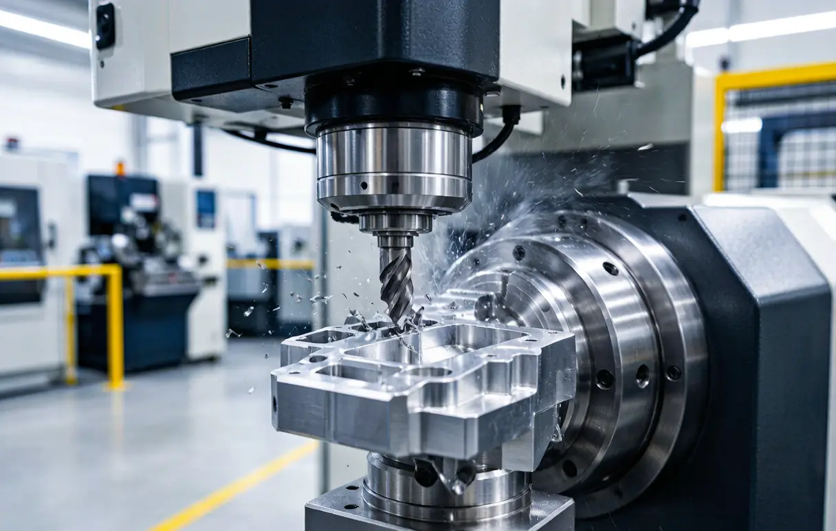
This article is written from a CNC-machining perspective. It focuses on what actually determines success in OEM UAV production: datum strategy, setup reduction, fixture design, toolpath choices, burr control, surface finishing allowances, inspection evidence, and the practical trade-offs between weight, stiffness, corrosion resistance, and cost.
If your program involves custom UAV hardware and you want a manufacturing route that goes from prototype to stable production, see JLYPT’s UAV machining capability page here:
Custom CNC UAV Parts Manufacturer
Table of Contents
- What an OEM UAV Components Manufacturer Really Delivers
- Where CNC Machining Fits in UAV Manufacturing
- UAV Component Categories and Typical CNC Processes
- Materials for UAV Hardware: Performance vs Machinability
- CNC Process Stack: 3-Axis, 3+2, 5-Axis, Turning, and Mill-Turn
- Datum Strategy and GD&T for UAV Assemblies
- Lightweighting Without Distortion: Thin Walls, Pockets, and Ribbing
- Threads, Inserts, and Wear Surfaces That Don’t Fail in the Field
- Surface Finishing: Anodize, Conversion Coating, Passivation, Paint Prep
- Inspection and QA Evidence: CMM, First-Article, Traceability
- DFM for UAV Parts: Design Moves That Cut Cost Without Losing Stiffness
- RFQ Checklist for an OEM UAV Components Manufacturer
- Three Case Studies (Prototype → Production Reality)
- Internal and External Links (SEO)
- Final Notes and Next Steps
1) What an OEM UAV Components Manufacturer Really Delivers
The phrase OEM UAV components manufacturer can mean different things depending on the drone segment (industrial, defense-adjacent, mapping, agriculture, inspection, consumer). In manufacturing terms, OEM-level support usually includes four pillars:
- Engineering-to-fabrication translation
Turning a CAD model into a stable process plan: datums, setups, tooling, fixturing, and inspection method. - Repeatable CNC machining
Not just “we can hit ±0.02 mm once,” but “we can hold the same geometry on batch after batch,” including after anodize or other finishing. - Supply chain coordination
Material control, finishing partners, fastener/inserts, packaging, labeling, and revision management. - Quality evidence
Documentation and inspection outputs that allow you to release product confidently, especially when multiple factories or assembly sites are involved.
Table 1 , Baseline Deliverables You Should Expect from an OEM UAV Components Manufacturer
Deliverable What it is Why it matters for UAV programs Typical frequency Quote with assumptions Process assumptions, finish, tolerances, lead time Prevents “surprises” after ordering Every RFQ Material certification (when requested) Lot-based material documentation Reduces risk of wrong alloy/temper Per material lot Inspection report Dimensional verification of key features Prevents assembly drift across batches Per lot or per request CMM report (when applicable) GD&T measurement output Validates true position/profile/runout First-article + periodic Process plan (internal) Setup plan, datums, toolpaths Enables repeatability and scaling Per part family Finishing coordination Masking, thickness allowances Avoids fit issues after anodize/coating Per order Packaging standard Protection against scratches/dings Cosmetic + functional surfaces stay intact Every shipment Revision control Correct model/drawing per PO Prevents mixed revision in assembly Always
A capable OEM UAV components manufacturer treats documentation, inspection, and finish planning as part of the deliverable, not optional extras.
2) Where CNC Machining Fits in UAV Manufacturing
CNC machining is often the shortest path to flight-ready mechanical hardware because it offers:
- Tight control of interfaces (bearing seats, dowel patterns, pilots, sealing lands)
- Predictable stiffness-to-weight outcomes (pockets, ribs, topology-inspired shapes)
- Fast iteration (rev changes do not require molding tools)
- Material flexibility (7075, 6061, titanium, stainless, engineering plastics)
CNC also pairs well with other UAV processes:
- Carbon fiber panels that still need CNC-drilled hole patterns
- Additive parts that require CNC finishing on datum surfaces
- Sheet metal parts that need post-bend machining for alignment features
For many programs, the most efficient strategy is hybrid: CNC for structure and interfaces, composites for large shells, additive for low-load fairings, and purchased parts for electronics and fasteners.
3) UAV Component Categories and Typical CNC Processes
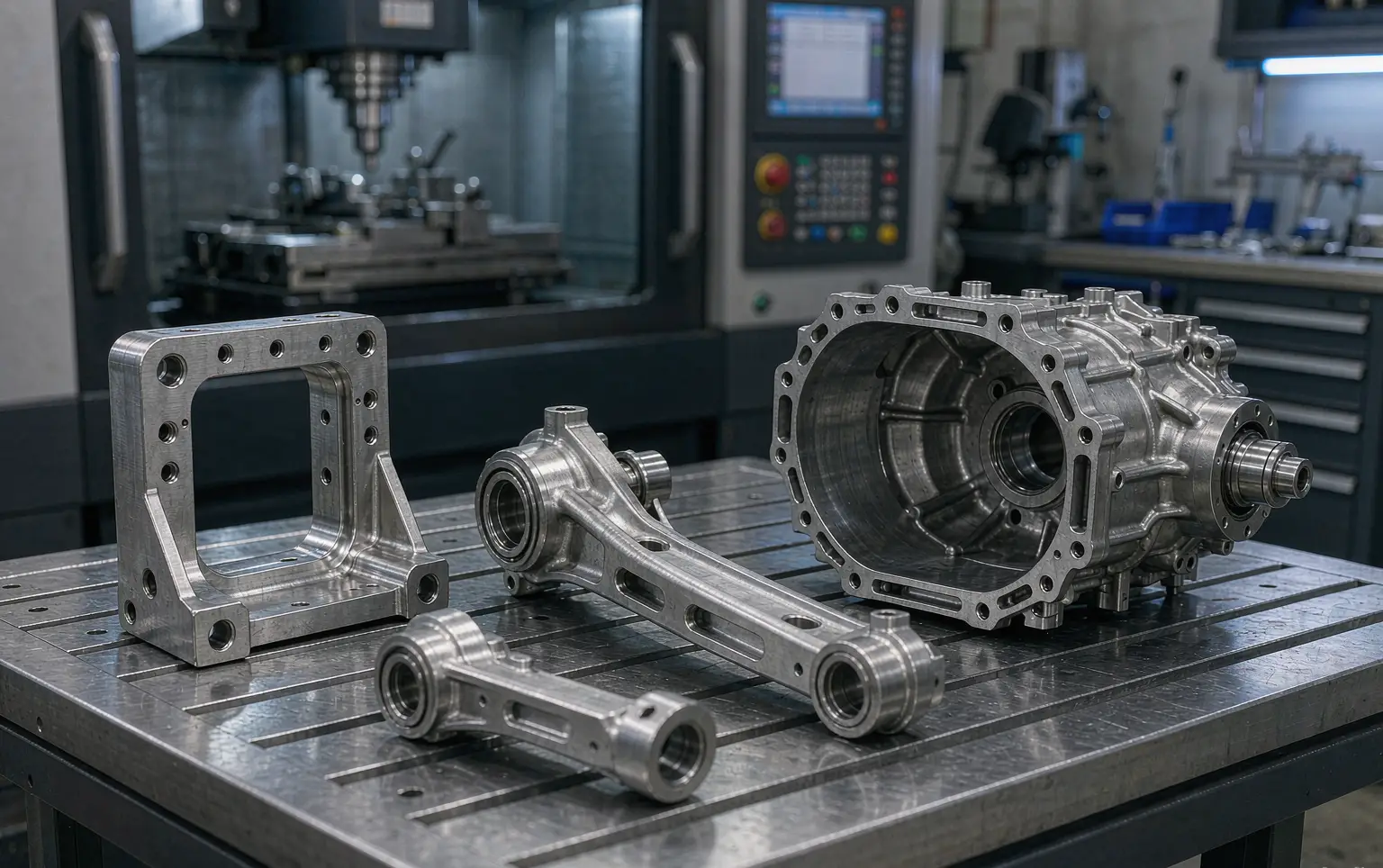
UAV assemblies combine high stiffness demands with tight packaging. The parts that benefit most from an OEM UAV components manufacturer with CNC capability are the ones that define alignment and load paths.
Table 2 , Common UAV Components and the CNC Method That Usually Wins
UAV component Typical function Recommended CNC process Common critical features Motor mount transfers thrust/torque 3-axis or 5-axis milling flatness, hole pattern true position, thread quality Arm joint / folding hinge carries bending loads 5-axis milling bore alignment, profile, bearing fits Central frame node distributes loads 5-axis milling multi-face positional accuracy Gimbal housing stabilizes payload 5-axis milling + finish passes coaxiality, surface finish, assembly datums Prop adapter / shaft hub rotating interface CNC turning + mill-turn runout, concentricity, thread form Landing gear bracket impact and vibration 3-axis milling perpendicularity, fillets, edge conditioning Avionics enclosure EMI/packaging 3+2 milling sealing land flatness, connector cutout location Battery tray / latch retention and shock 3-axis milling slot width, latch fit, wear surfaces Sensor mount optical alignment 5-axis milling angularity, datum stability Heat sink plate thermal management 3-axis milling flatness, fin geometry
A practical sign you’re working with the right OEM UAV components manufacturer: they’ll ask what the part does in the assembly (load path, alignment requirement, service/maintenance) before they talk about machine time.
4) Materials for UAV Hardware: Performance vs Machinability
Material choice in UAV manufacturing is usually a three-way trade:
- mass (density)
- stiffness/strength
- corrosion and field durability
Table 3 , UAV-Relevant Materials and CNC Machining Notes
Material Why UAV designers choose it CNC machining behavior Best-use parts Finishing notes Aluminum 6061-T6 cost-effective, corrosion resistant easy machining, stable housings, brackets, trays anodize, conversion coating Aluminum 7075-T6 high strength-to-weight machines well but notch-sensitive motor mounts, joints, structural nodes anodize/hard anodize; add radii Titanium (Ti-6Al-4V) strength + corrosion at low weight low thermal conductivity; tool wear fastener-like parts, high-load joints careful surface integrity; passivation Stainless 17-4PH strength + wear resistance depends on condition; can distort after heat treat shafts, lugs, wear blocks passivation; manage heat treat sequence Stainless 316 corrosion (marine environments) gummy; work hardening fasteners, exposed brackets passivation; sharp tools Engineering plastics (Delrin/POM, Nylon, PEEK) weight, damping, insulation easy (POM) to demanding (PEEK) covers, isolators, cable guides avoid stress cracking; control burrs Carbon fiber plate (CFRP laminate) stiffness/weight abrasive; dust control needed panels, decks edge sealing; carbide tooling
A strong OEM UAV components manufacturer helps you pick the “right enough” material: not over-spec’d (cost and lead time), but not under-built (field failures and warranty pain).
5) CNC Process Stack for an OEM UAV Components Manufacturer
UAV parts often look simple until you inspect the interfaces: multi-face datums, angled patterns, coaxial bores, and thin-wall pockets. That’s where process selection matters.
5.1 3-Axis CNC Milling
Best for plates, simple brackets, trays, and parts with most features accessible from one or two orientations.
5.2 3+2 (Positional 5-Axis)
A practical middle ground: it reduces setups for multi-face parts without the complexity of continuous 5-axis surfacing.
5.3 5-Axis Simultaneous Milling
Often the difference between a “prototype that fits” and a “production part that repeats,” especially for:
- complex arm joints
- gimbal housings
- central frame nodes with compound angles
- deep pockets requiring short tools and stable tool engagement
5.4 CNC Turning
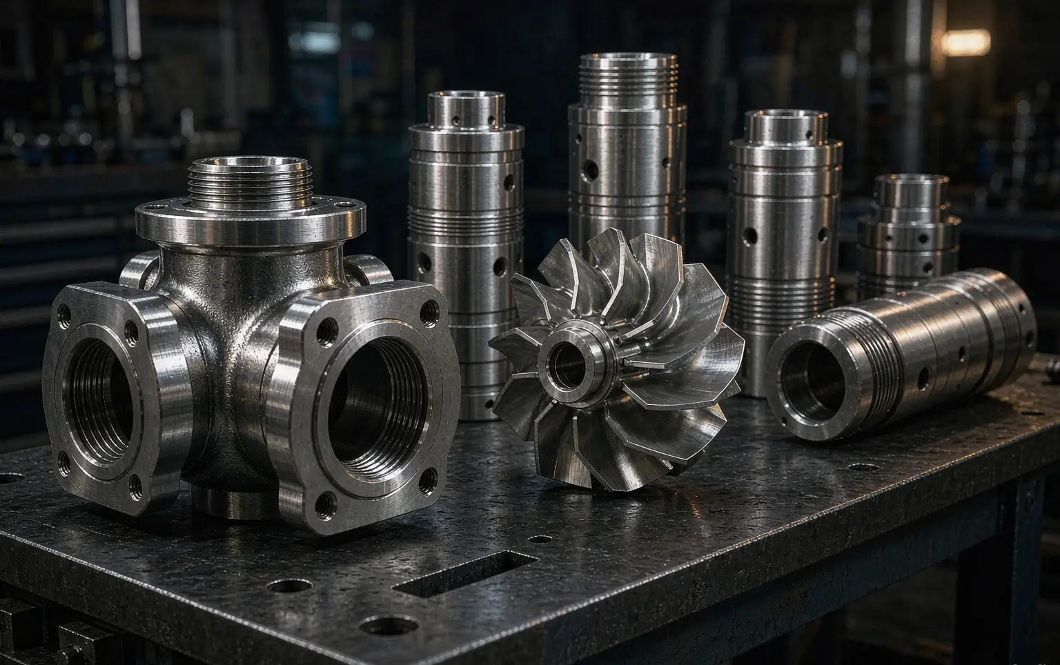
Critical for rotational parts: hubs, shafts, spacers, collars, threaded adapters.
5.5 Mill-Turn (Multi-Task)
Ideal when you need turned accuracy (runout/coaxiality) plus milled features (flats, cross-holes, keyways) without re-chucking.
Table 4 , Process Selection Matrix (UAV-Oriented)
Requirement Recommended process Why it matters to an OEM UAV components manufacturer Typical inspection focus Tight multi-face alignment 3+2 or 5-axis fewer setups = less datum stack-up true position, perpendicularity Coaxial bores + side features mill-turn keeps axis features in one clamping runout, coaxiality Lightweight pocketing 5-axis + HSM strategy stable engagement, shorter tools wall thickness, flatness High cosmetic requirements controlled finishing passes reduces tool witness and chatter Ra, visual standard Small threaded hole arrays rigid tapping / thread milling consistent thread form go/no-go, thread depth High-volume repetition fixture + probing plan stable cycle time + low scrap in-process checks
When evaluating an OEM UAV components manufacturer, ask: “How many setups will this part take, and what are the datums in each setup?” That question reveals process maturity quickly.
6) Datum Strategy and GD&T for UAV Assemblies
UAV assemblies are essentially alignment systems: motor thrust lines, propeller planes, gimbal axes, camera boresights, sensor baselines. A part can be “in tolerance” yet still cause assembly drift if the datum scheme is wrong.
A competent OEM UAV components manufacturer will focus on:
- functional datums (how the part actually mounts)
- setup datums (how the part is held during machining)
- inspection datums (how the part is measured)
Table 5 , UAV Features That Deserve GD&T (Because They Drive Assembly Performance)
Feature Why it’s critical in UAVs Recommended GD&T control (typical) Notes Motor bolt circle affects thrust alignment & vibration true position to a datum plane/axis clamp distortion can shift pattern Bearing seats vibration + wear cylindricity / runout prefer single-setup finishing Gimbal axis bores stabilization accuracy coaxiality / true position inspect with CMM when possible Frame mating plane frame squareness flatness + perpendicularity finish late in process Dowel holes / locating pins repeatable assembly true position avoid “slotting” designs unless intentional Sensor mount angle calibration drift angularity / profile ensure datum scheme matches calibration method
Even if your drawing doesn’t call out full GD&T, your OEM UAV components manufacturer should think in GD&T terms, because that’s how you protect functional geometry.
7) Lightweighting Without Distortion: Thin Walls, Pockets, and Ribbing
UAV designers understandably chase grams. The trap is creating a part that is light in CAD but unstable in machining (and later in service).
Common distortion triggers:
- deep pockets near edges
- non-uniform wall thickness
- clamping on thin flanges
- removing too much stock from one side
Table 6 , Lightweighting Moves That CNC Shops Prefer (Because They Stay Straight)
Goal Risky approach Better approach Why an OEM UAV components manufacturer prefers it reduce mass thin flat plate with big pocket add ribs + keep walls uniform machines flatter, higher stiffness keep strength sharp inside corners generous internal radii less stress concentration, larger tools save cycle time tiny corner radii everywhere standardize radii fewer tool changes, faster improve repeatability many isolated thin bosses connect bosses with ribs reduces vibration and chatter simplify finishing mixed cosmetic surfaces define cosmetic zones clear visual standard
Table 7 , Shop-Level Distortion Controls Used in CNC Machining
Control method What it does When it’s useful staged roughing + rest finishing balances residual stress thin-wall aluminum nodes leaving uniform stock for finish improves stability frame plates, housings custom nest fixtures supports thin geometry gimbal shells, arm joints in-process probing catches shift before scrap multi-setup parts finishing datum faces last locks geometry at end sealing lands, mating planes
A reliable OEM UAV components manufacturer will talk about distortion as a system problem: design + setup + removal strategy, not just “machine accuracy.”
8) Threads, Inserts, and Wear Surfaces That Survive Field Service
UAVs live in a world of repeated assembly: arms fold, payloads swap, fasteners get over-torqued, vibration works everything. Thread and wear design is where many “good-looking” parts fail.
8.1 Threads: tap vs thread mill
- tapping is fast, but needs rigid conditions and controlled chip evacuation
- thread milling is slower but offers better control for tough materials and blind holes
8.2 Inserts (Helicoil-style, press-fit nuts, heat-set)
In aluminum structures, inserts often make sense for serviceability. The critical point: insert installation can deform thin walls if the design doesn’t provide enough material around the hole.
Table 8 , Thread and Insert Decisions (UAV Hardware)
Need Best practice Why it matters to an OEM UAV components manufacturer frequent removal use inserts in aluminum prevents thread stripping in field vibration environment controlled thread engagement torque consistency improves reliability tight packaging avoid extremely shallow threads reduces pull-out failures corrosion avoid dissimilar metal traps manage galvanic pairs with coatings precision alignment use dowels + bolts bolts clamp, dowels locate
9) Surface Finishing: Anodize, Conversion Coating, Passivation, Paint Prep
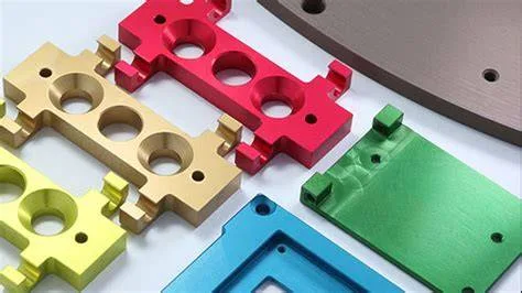
Finishing is where many UAV assemblies gain (or lose) consistency. An OEM UAV components manufacturer should plan finishing at the quoting stage because finishing changes dimensions and friction behavior.
Table 9 , Common UAV Finishes and CNC Planning Notes
Finish Typical UAV purpose Dimensional impact CNC planning notes Anodize (decorative) corrosion + appearance thickness build protect critical fits; define cosmetic standard Hard anodize wear surfaces, sliding zones more build + hardness allow for growth; avoid on press-fit bores unless designed Conversion coating conductivity + corrosion minimal build good for grounding surfaces Passivation (stainless) corrosion negligible build ensure surface cleanliness Electroless nickel (when used) wear + corrosion uniformity controlled thickness build specify thickness; mask precision areas Paint/powder prep appearance, UV protection varies maintain surface finish and edge quality
Table 10 , “Finish-Sensitive” UAV Features (Plan These Early)
Feature Why finish matters Typical approach bearing seat bore thickness affects fit mask or size after finish press-fit dowel holes small build changes interference mask or ream after finish electrical grounding pad anodize blocks conductivity mask grounding points sealing land scratches become leaks packaging + protective film sliding interface finish changes friction choose hard anodize or coating deliberately
Good finishing outcomes come from upstream planning, another hallmark of a serious OEM UAV components manufacturer.
10) Inspection and QA Evidence: CMM, First-Article, Traceability
UAV programs vary in quality requirements, but scaling always increases the cost of mistakes. The right inspection plan prevents field failures and production delays.
10.1 Measurement tools that matter
- CMM for position/profile/coaxiality on complex parts
- bore gages and pin gages for fast production checks
- surface plate + height gage for flatness and basic geometry
- runout checks for rotating components
- surface roughness tester for sealing lands and bearing seats
Table 11 , Inspection Outputs You Can Request from an OEM UAV Components Manufacturer
Output What you get Best used for First-article inspection (FAI-style report) full dimension check on first-off new part release, rev changes CMM report GD&T verification hole patterns, profiles, gimbal axes Sampling plan report periodic dimensional snapshots production stability Material cert (if required) alloy and heat/temper evidence structural and critical parts Coating thickness verification thickness range finish-sensitive fits
Table 12 , Practical Traceability Levels for UAV Programs
Program stage Suggested traceability Why early prototype basic lot labeling speed, low overhead pilot production material lot + revision control prevents mixed builds production ramp inspection records per batch supports root-cause analysis regulated or safety-critical full cert package + controlled docs audit readiness
A capable OEM UAV components manufacturer will match the QA package to your risk level, without forcing unnecessary bureaucracy.
11) DFM for UAV Parts: The Changes That Usually Save You Time and Money
If you want a drone program to scale, DFM is not optional. It’s the difference between “expensive art” and a part that can be produced in batches with stable quality.
Table 13 , DFM Moves That Reduce Cost and Improve Repeatability
Design element Common problem Better design choice Benefit tiny internal corner radii requires small tools, long cycle use standard radii faster machining, better finish deep narrow pockets chatter and wall taper open pocket access stable tool engagement unnecessary tight tolerances inspection burden tighten only critical features lower cost, faster lead time ambiguous datums assembly drift define functional datums stable alignment thin unsupported tabs warp and vibration add ribs or thickness better yield mixed fastener standards supply complexity standardize sizes/threads easier assembly and service
A practical OEM UAV components manufacturer will provide DFM feedback in RFQ review, often with a short list of “change these three features and your part becomes predictable.”
12) RFQ Checklist for an OEM UAV Components Manufacturer
An RFQ that’s missing key details forces assumptions. Assumptions become disputes, or scrap. Use this checklist to keep quotes comparable and outcomes stable.
Table 14 , RFQ Checklist (Send This with Your CAD/Drawings)
Item What to provide Why it matters CAD + drawing STEP + PDF drawing prevents interpretation gaps revision level rev letter/number avoids mixed builds material + temper e.g., 7075-T6 controls machinability/strength finish requirement anodize type, color, masking prevents fit issues critical features list “bearing bores, motor pattern” focuses inspection on what matters tolerance philosophy general + critical tolerances controls cost and process quantity and forecast protos + expected ramp allows fixture and process planning packaging expectations cosmetic surfaces, films reduces shipping damage documentation inspection report, CMM, certs sets release criteria assembly context mating parts/datums improves datum strategy
If a supplier doesn’t ask clarifying questions, they might not be operating like an OEM UAV components manufacturer: they’re simply quoting machining time.
13) Three Case Studies (Prototype → Production Reality)
The following examples reflect common UAV manufacturing scenarios. Details are generalized to protect customer confidentiality while preserving engineering relevance.
Case Study 1 , 7075-T6 Motor Mount: Vibration Control Through Datum Discipline
Part type: multi-bolt motor mount with weight-reduction pockets
Why it mattered: the customer experienced vibration and inconsistent motor alignment across builds.
Key technical requirements
- bolt circle true position relative to a primary mounting face
- consistent flatness on the motor interface
- controlled edge breaks to reduce stress risers and handling cuts
Manufacturing challenges
- thin pockets near the mounting face caused slight face movement after unclamping
- multiple setups created datum transfer error across batches
Approach an OEM UAV components manufacturer would use
- re-ordered operations: rough pockets → stabilize → finish the datum face late
- minimized setups using positional multi-face machining where appropriate
- controlled tool engagement to avoid chatter marks that can seed fatigue
- defined a consistent deburr/edge-break method to prevent sharp transitions
Result
- more consistent motor thrust-line alignment
- reduced vibration-related complaints in test flights
- better repeatability from small batch to larger batch production
Case Study 2 , 5-Axis Gimbal Housing: Coaxiality, Surface Finish, and Assembly Feel
Part type: compact gimbal housing with multiple bores and angled faces
Why it mattered: gimbal performance depended on axis alignment and smooth motion.
Key technical requirements
- coaxial bores for bearing seats
- tight profile control on mating features
- cosmetic surface zones (visible to end users)
Manufacturing challenges
- multiple angled faces increased setup count if done conventionally
- long tool reach risked chatter inside cavities
- finishing could change fit if not planned
Approach an OEM UAV components manufacturer would use
- 5-axis machining to reduce setups and preserve the datum scheme
- finishing passes planned for consistent Ra on bearing-related features
- inspection plan combining bore gaging and CMM verification of positional relationships
- finish allowances reviewed early to prevent post-anodize fit surprises
Result
- smoother assembly feel with less variability
- stable gimbal alignment across pilot and production lots
- fewer reworks related to bore fit and cosmetic rejection
Case Study 3 , CNC-Turned Shaft Adapter (Mill-Turn): Runout Reduction by Eliminating Re-Chucking
Part type: prop or coupling adapter requiring precision turned features plus milled flats/holes
Why it mattered: even small runout deviations amplified vibration and bearing wear.
Key technical requirements
- tight runout on functional diameters
- accurate thread form and thread start consistency
- milled features clocked accurately to the rotational axis
Manufacturing challenges
- re-chucking between turning and milling introduced axis misalignment
- thread burr control impacted assembly torque consistency
Approach an OEM UAV components manufacturer would use
- mill-turn workflow to keep turning and milling in one clamping
- controlled threading strategy (tapping or thread milling depending on material)
- runout verification with dedicated inspection method (indicator/CMM as appropriate)
- consistent deburr at thread starts and cross-holes to reduce assembly damage
Result
- reduced runout variation batch-to-batch
- fewer vibration issues in system testing
- improved field serviceability due to cleaner threads and edges
14) Internal and External Links (SEO)
Internal Links (JLYPT)
- Custom UAV parts capability : Custom CNC UAV Parts Manufacturer
- JLYPT homepage : JLYPT
External Technical References (Plain URLs)
- ISO standards overview: ISO standards
- ASTM standards overview: ASTM standards
- NIST measurement and metrology resources: NIST
(These are general engineering references. Always follow your drawing notes, specifications, and purchase order requirements.)
15) Final Notes: How to Choose the Right OEM UAV Components Manufacturer
A dependable OEM UAV components manufacturer is not defined by one machine or one tolerance claim. It’s defined by a manufacturing system: a clear datum strategy, minimized setups, stable workholding, finish-aware tolerancing, controlled deburring, and inspection evidence that matches the risk of your application.
If your UAV program is moving from prototype builds to stable production, and you want CNC machining support with a practical engineering mindset, use this page to start the conversation with JLYPT:
Custom CNC UAV Parts Manufacturer
Internal Links (Use in Article)
- Primary internal link : Custom CNC UAV Parts Manufacturer
- Additional internal link : JLYPT