
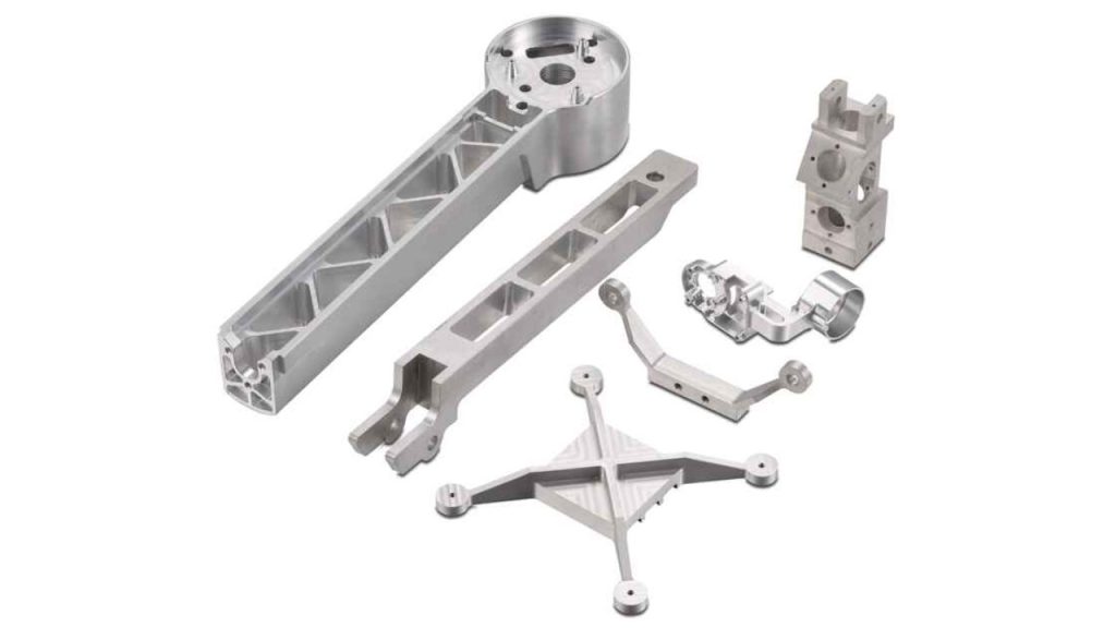
CNC Drone Motor Mounts: A Practical CNC Machining Guide for Stiffer, Lighter, Quieter UAV Propulsion
Motor mounts look simple until they fail a flight test. In a drone, the motor mount is not just a bracket—it’s the mechanical “truth” of the propulsion system. It defines thrust-line direction, controls vibration transmission into the frame, protects the motor from misalignment, and survives repeated thermal cycles and service events (removing motors, replacing arms, swapping propellers). This is a manufacturing-focused playbook on CNC drone motor mounts—how to design them for machining, how to choose materials and finishes, which GD&T controls actually matter, and how an OEM-style CNC process keeps performance consistent from prototype to production. If you’re sourcing custom UAV parts and want a supplier that understands CNC process planning, inspection, and finishing allowances, JLYPT’s capability page is here:
https://www.jlypt.com/custom-cnc-uav-parts-manufacturer/
Table of Contents
- Why CNC Drone Motor Mounts Decide Flight Quality
- Performance Requirements: Alignment, Vibration, Heat, and Serviceability
- Common Motor Mount Architectures (and What CNC Likes)
- Material Selection for CNC Drone Motor Mounts
- CNC Process Options: 3-Axis, 3+2, 5-Axis, and Hybrid Methods
- Workholding and Datum Strategy for Repeatable Bolt Patterns
- Critical GD&T for CNC Drone Motor Mounts
- Lightweighting Without Warping: Pocket Strategy, Wall Control, and Ribbing
- Threads That Don’t Strip: Tapping vs Thread Milling vs Inserts
- Surface Finish and Coatings: Anodize, Hardcoat, Conversion Coating, Passivation
- Inspection Plans: From Shop-Floor Gauging to CMM Reports
- DFM Checklist for Faster Quotes and Higher Yield
- Cost Drivers and Lead-Time Levers
- 3 Case Studies: Prototype Lessons That Became Production Standards
- RFQ Package Template (What to Send Your CNC Supplier)
- Links (Internal + External) and Next Steps
1) Why CNC Drone Motor Mounts Decide Flight Quality
A drone motor can be perfectly balanced and still produce ugly vibration if the mount is out of plane, the bolt pattern shifts, or the mount flexes under thrust. Unlike many brackets, a motor mount is tied directly to rotating mass at high RPM, so tiny geometric errors can show up as:
- oscillation at specific throttle bands
- accelerated bearing wear
- loosening fasteners despite threadlocker
- noisy video stabilization and “jello” artifacts
- cracked arms near the motor interface
- inconsistent thrust vectors that force the flight controller to compensate That’s why CNC drone motor mounts are a high-value part to machine correctly. CNC isn’t just about holding a generic tolerance; it’s about maintaining functional geometry (datums, perpendicularity, and true position) through machining, deburring, and finishing.
2) Performance Requirements: Alignment, Vibration, Heat, and Serviceability
2.1 Alignment and thrust-line control
Your motor mount defines where the motor axis points relative to the arm and frame. Even a small angular error can create constant trim corrections, reduce efficiency, and introduce cross-coupled vibrations.
2.2 Vibration transmission
A mount must be stiff enough to resist bending and torsion, yet not act like a tuning fork. The “right” stiffness depends on the arm length, motor KV, prop size, and payload sensitivity.
2.3 Thermal behavior
Mount geometry can help or hurt cooling. Some drones rely on the mount as a heat spreader for the motor base or nearby ESC components.
2.4 Serviceability and field repair
Motor mounts are frequently removed. Threads must survive repeated cycles; edges should not cut wiring; fastener access must be practical.
Table 1 — Typical Functional Requirements for CNC Drone Motor Mounts
| Requirement | What it controls | What goes wrong if ignored | CNC/QA lever |
|---|---|---|---|
| Mounting face flatness | motor sits without rocking | vibration, loose bolts | face milling strategy + inspection |
| Bolt circle true position | motor axis consistency | thrust-line shift, uneven preload | datum scheme + CMM/optical check |
| Perpendicularity to arm interface | motor axis vs arm axis | yaw/roll coupling, drift | multi-face machining + probing |
| Thread quality | clamp stability | stripped threads, inconsistent torque | thread milling/inserts + gauges |
| Surface finish (Ra) | clamp friction & seating | bolt relaxation, fretting | finishing passes + deburr control |
| Edge conditioning | wiring safety & fatigue | wire damage, crack initiation | controlled chamfer / radii |
| Coating allowance | final fit consistency | bolt holes tight after anodize | mask/ream strategy |
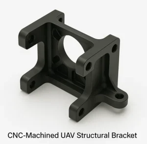
3) Common Motor Mount Architectures (and What CNC Likes)
Even within “motor mount,” there are multiple architectures. The best design depends on your arm style, motor size, and assembly strategy.
Table 2 — Motor Mount Styles and CNC Implications
| Mount style | Typical use | CNC strengths | CNC pitfalls to avoid |
|---|---|---|---|
| Flat plate (bolt pattern + center bore) | lightweight quads | fast 3-axis machining | warp after pocketing; thin tabs |
| Cup / shallow pocket mount | protects motor base, hides fasteners | good stiffness-to-weight | deep pocket chatter, tool reach |
| Clamp-style mount | tubular arms, folding arms | strong retention | distortion from clamp slots; burrs |
| Angled interface mount | VTOL/fixed-wing thrust vectoring | needs 3+2 or 5-axis | datum transfer errors with many setups |
| Integrated arm-end mount | structural node | single-piece stiffness | heavy machining time; careful lightweighting |
| Mount + ESC plate combo | compact builds | reduces part count | heat + coating considerations |
| Well-made CNC drone motor mounts typically reduce parts and setups while keeping functional datums easy to inspect. |
4) Material Selection for CNC Drone Motor Mounts
Material drives stiffness, fatigue life, corrosion behavior, and coating options. For CNC drone motor mounts, the most common decision is 6061 vs 7075—then special cases where titanium or stainless inserts make sense.
Table 3 — Material Comparison for CNC Drone Motor Mounts
| Material | Why it’s used | Machining notes | Where it shines | Watch-outs |
|---|---|---|---|---|
| 6061-T6 aluminum | cost-effective, corrosion friendly | stable, forgiving | general mounts, plates | lower strength than 7075 |
| 7075-T6 aluminum | high strength-to-weight | machines well, strong | high-load mounts, racing/heavy thrust | more sensitive to sharp corners |
| 2024 aluminum (when specified) | fatigue performance | good machinability | aerospace-style fatigue designs | corrosion protection needed |
| Ti-6Al-4V titanium | strength + corrosion at lower weight | slower cutting, tool wear | heavy-lift, harsh environments | cost, heat management |
| 17-4PH stainless | wear resistance, strength | depends on heat treat state | inserts, bushings, clamp surfaces | heat treat distortion planning |
| 303/304 stainless | general corrosion | gummy, can work harden | hardware-adjacent components | burr control, tool sharpness |
| POM (Delrin) / Nylon | damping, insulation | fast, clean | isolators, sacrificial mounts | creep under load |
| CFRP plate (laminate) | stiffness-to-weight | abrasive, dust control | plates with bonded inserts | edge sealing, delamination risk |
| A practical rule: if the mount is thin and highly pocketed, 7075 often buys you stiffness margin. If the mount is thicker and less stressed, 6061 can be more cost-efficient and stable. |
5) CNC Process Options for CNC Drone Motor Mounts
5.1 3-axis milling (most common)
For flat plates and mounts with features accessible from one side, 3-axis is the throughput winner—especially with a fixture that supports multiple parts per cycle.
5.2 3+2 positional machining (indexing)
If you need a few angled features (wire exits, chamfered interfaces, side holes), indexing reduces manual refixturing and improves repeatability.
5.3 5-axis machining (continuous or indexed)
5-axis makes sense for:
- mounts integrated into complex arm-end nodes
- angled thrust-line mounts
- parts requiring multi-face accuracy with fewer setups
5.4 Hybrid: mill + secondary ops
Some mounts combine CNC milling with press-fit bushings, thread inserts, or post-process reaming to control coating effects.
Table 4 — Choosing the Process Route
| Part characteristic | Best-fit CNC route | Why | Typical yield risk |
|---|---|---|---|
| Plate mount, simple pockets | 3-axis + pallet/fixture | fastest cycle | warp if pocketing aggressive |
| Bolt circle + deep counterbores | 3-axis with rigid drilling cycle | positional stability | burrs at hole breaks |
| Angled arm interface | 3+2 or 5-axis | fewer setups | datum transfer errors |
| Integrated mount node | 5-axis + HSM | tool access + surface quality | heat + thin wall chatter |
| High volume, stable rev | dedicated fixture + probing | repeatability | fixture wear, chip packing |
| A real CNC drone motor mounts program is less about “which machine” and more about setup count, datum control, and inspection strategy. |
6) Workholding and Datum Strategy for Repeatable Bolt Patterns
Bolt patterns are deceptively hard. You can machine holes “accurately” and still miss functional alignment if the datum is inconsistent between setups or clamping distorts the part.
6.1 Recommended datum approach (practical)
- Datum A: motor mounting face (the surface that seats the motor)
- Datum B/C: two orthogonal locating features tied to the arm interface (edges, dowel holes, or a precision pocket)
6.2 Workholding options
- Soft jaws with a locating step (great for thicker mounts)
- Vacuum fixtures (for plate-style mounts, if leakage is managed)
- Dedicated nests with pins (for multi-part arrays and repeatability)
Table 5 — Workholding Methods for CNC Drone Motor Mounts
| Workholding | Best for | Advantages | Risks |
|---|---|---|---|
| Vise + parallels | prototypes | simple, fast | clamp distortion |
| Soft jaws (machined) | repeat runs | consistent location | jaw wear; chip contamination |
| Fixture plate + dowel pins | batches | excellent repeatability | upfront fixture time |
| Vacuum fixture | thin plates | minimal clamp marks | bowing if pockets relieve stress |
| Tombstone/pallet | higher volume | throughput + automation ready | needs stable process |
| A supplier who routinely builds CNC drone motor mounts will talk about location strategy (pins/steps) as much as cutting parameters. |
7) Critical GD&T for CNC Drone Motor Mounts
If you want mounts that assemble smoothly and fly consistently, you need GD&T that matches function. Over-tolerancing everything is expensive; under-tolerancing the wrong features creates hidden performance variation.
Table 6 — GD&T Controls That Matter Most
| Feature | Why it’s mission-critical | Suggested control (typical) | Measurement method |
|---|---|---|---|
| Motor mounting face | defines seating | Flatness | surface plate / CMM |
| Bolt circle holes | defines axis & clamp symmetry | True position to datums | CMM / optical |
| Center pilot bore (if used) | concentric seating | Position / circularity | bore gauge / CMM |
| Arm interface face | motor axis relationship | Perpendicularity to A | CMM / height gauge |
| Counterbore/spotface | bolt head seating | Depth + flatness | depth mic / CMM |
| Side pocket walls | clearance & stiffness | profile (when needed) | CMM sampling |
Practical tolerance philosophy
- Put tight controls on: bolt circle position, mounting face flatness, and any pilot bore.
- Keep general tolerances looser elsewhere to reduce machining time and inspection cost. That’s how CNC drone motor mounts stay affordable without becoming “random” in performance.
8) Lightweighting Without Warping: Pocket Strategy, Wall Control, Ribbing
Lightweighting is where many mounts fail—either in machining (warped plates) or in service (cracks at sharp transitions).
8.1 CNC-friendly lightweighting moves
- Keep wall thickness uniform where possible
- Use generous internal fillets (bigger tools, less stress)
- Avoid isolated thin “islands” around bolt holes
- Prefer ribs that connect bosses rather than thin pads
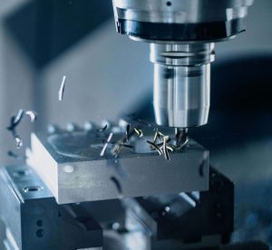
Table 7 — Lightweighting Rules That Improve CNC Yield
| Goal | Common mistake | Better CNC-friendly design | Why it works |
|---|---|---|---|
| reduce mass | huge deep pocket under face | staged pockets + ribs | reduces stress release |
| keep stiffness | thin ring around bolt circle | thicker local pads + ribs | controls clamp load distribution |
| avoid cracks | sharp internal corners | fillets sized to tooling | lowers stress concentration |
| reduce cycle time | many micro-pockets | fewer larger pockets | less toolpath overhead |
| maintain flatness | pocket both sides unevenly | balanced material removal | less bowing |
8.2 Toolpath choices that matter
For aluminum mounts, high-speed machining strategies (adaptive clearing / constant engagement) reduce tool load spikes and help thin features survive.
Table 8 — Machining Strategy Choices (What They Affect)
| Strategy | Typical use | Benefit | Risk if misapplied |
|---|---|---|---|
| Adaptive clearing | roughing pockets | stable tool load | thin walls can chatter if unsupported |
| Rest machining | finishing corners | consistent radii | extra cycle time if overused |
| Climb milling (finishing) | surface quality | better finish | requires rigid setup |
| Trochoidal slotting | narrow slots | lower heat | toolpath tuning needed |
| Spring pass | thin walls | reduces deflection error | can smear if tool is dull |
| For CNC drone motor mounts, the best shops separate “roughing for speed” from “finishing for geometry,” and they leave consistent stock for the finishing pass. |
9) Threads That Don’t Strip: Tapping vs Thread Milling vs Inserts
Motor mounts are repeatedly serviced. Threads see vibration, heat, and sometimes over-torque. Thread strategy is a reliability decision, not a minor detail.
9.1 Tapping
Fast and cost-effective in aluminum if the hole is well-prepared and chips evacuate cleanly.
9.2 Thread milling
Excellent control, especially for:
- blind holes
- tougher materials
- fine threads
- avoiding tap breakage in expensive parts
9.3 Inserts (wire inserts / solid inserts)
Great for serviceability and wear resistance—especially in 6061 mounts where repeated disassembly is expected.
Table 9 — Thread Strategy Guide for CNC Drone Motor Mounts
| Condition | Recommended | Why | Notes |
|---|---|---|---|
| prototype, low cycles | tap | fast, low cost | verify torque behavior |
| production, frequent service | insert + thread milling | high durability | ensure sufficient wall thickness |
| titanium/stainless threads | thread milling | reduces risk | manage burr control |
| weight-critical design | tapped holes in 7075 | stronger base metal | use proper engagement length |
| vibration severe | insert + correct preload | better thread integrity | add locking method (as specified) |
| A supplier experienced with CNC drone motor mounts will also control edge break around threads to reduce galling and improve fastener seating. |
10) Surface Finish and Coatings for CNC Drone Motor Mounts
Finishing is not cosmetic-only. It influences corrosion resistance, friction under bolt heads, and dimensional changes in holes and bores.
10.1 Anodize (Type II)
Often chosen for appearance + corrosion resistance.
10.2 Hard anodize / hardcoat (Type III)
Used where abrasion or fretting is likely (bolt head seating areas, clamp regions, sliding interfaces).
10.3 Conversion coating
Useful when electrical conductivity is needed on mating surfaces, depending on the system grounding strategy.
Table 10 — Coating Choices and CNC Planning Impacts
| Finish | Why used on motor mounts | Dimensional impact | CNC planning tip |
|---|---|---|---|
| anodize | corrosion + aesthetics | thickness build | allow clearance; consider masking |
| hard anodize | wear resistance | more build | avoid on tight bores unless designed |
| conversion coating | conductivity + corrosion | minimal | specify areas requiring conductivity |
| passivation (stainless parts) | corrosion resistance | negligible | ensure proper cleaning/deburr |
10.4 Masking and post-finish sizing
If bolt holes are sensitive, you may:
- mask critical fits
- ream after finishing (when process allows)
- design clearance so finish build doesn’t matter This is a major success factor for production-grade CNC drone motor mounts.
11) Inspection Plans: From Shop-Floor Gauging to CMM
Inspection is where “looks right” becomes “is right.” For motor mounts, the most valuable checks are the ones tied to function.
Table 11 — Recommended Inspection Checklist (Motor Mount Focus)
| Feature | Target characteristic | Shop-floor tool | When to CMM |
|---|---|---|---|
| mounting face | flatness | surface plate + indicator | if vibration issues persist |
| bolt circle | true position | pin gauges + template / optical | for tight patterns or high volume |
| pilot bore | size + roundness | bore gauge | if coaxiality matters |
| perpendicularity | face-to-face relationship | height gauge | for angled interfaces |
| threads | go/no-go | thread gauges | always |
| coating thickness (if required) | thickness range | coating gauge | when fits are finish-sensitive |
| A serious supplier of CNC drone motor mounts can provide first-article reports, in-process control checks, and periodic sampling—scaled to your program stage. |
12) DFM Checklist for Faster Quotes and Higher Yield
Design for manufacturing is not about “making it cheaper at all costs.” It’s about removing ambiguity and avoiding geometry that forces fragile machining or overly complex inspection.
Table 12 — DFM Checklist for CNC Drone Motor Mounts
| Area | DFM recommendation | Why it helps |
|---|---|---|
| corner radii | use standard radii | fewer tools, faster finishing |
| pocket depths | avoid extreme depth-to-width | reduces chatter |
| hole callouts | specify which holes are critical | focuses inspection and cost |
| datum scheme | define A/B/C to match assembly | prevents drift |
| edge breaks | define chamfer/radius standard | consistent deburr and safety |
| coating notes | specify type + masked areas | prevents fit surprises |
| tolerance stacking | tighten only functional features | lowers cycle time + scrap |
| If you want a quote that doesn’t come back with a long list of assumptions, this checklist is the simplest way to help your CNC drone motor mounts supplier succeed. |
13) Cost Drivers and Lead-Time Levers
Motor mounts can be cheap—or surprisingly expensive—depending on a few design and process choices.
Table 13 — What Actually Drives Cost on CNC Drone Motor Mounts
| Cost driver | Why it costs more | Typical fix |
|---|---|---|
| many setups | extra handling and alignment | redesign for single-direction access or 3+2 |
| tiny radii | small tools, slow feeds | standardize radii |
| deep pockets | long tools, chatter risk | adjust depth or add ribs |
| ultra-tight general tolerances | inspection time explodes | tighten only critical features |
| cosmetic class on all faces | extra finishing and handling | define cosmetic zones |
| hard anodize without planning | post-finish rework | mask/allow clearance in design |
| Lead time is often improved more by simplifying setups than by “paying for faster machining.” |
14) Three Case Studies: CNC Drone Motor Mounts in the Real World
Below are three representative examples of how motor mounts evolve from “first workable” to “production stable.” Details are generalized, but the manufacturing lessons are exactly what you can apply to your project.
Case Study 1 — 7075 Plate Mount for a High-RPM Racing Platform
Problem: Vibration spikes at a narrow throttle band, inconsistent between builds. Initial design
- ultra-thin plate with aggressive underside pocketing
- tight bolt circle but vague datum definition
- cosmetic finishing everywhere (extra handling) Manufacturing observations
- pocketing released stress and created a slight bow
- bolt pattern was “in tolerance,” but thrust-line consistency varied due to datum ambiguity
- deburr variability changed bolt head seating friction Process + design adjustments
- defined Datum A as the motor seating face; controlled flatness there
- changed pocket strategy: rough evenly, leave uniform stock, finish face late
- standardized edge break and spotface finish pass
- focused inspection on: face flatness + bolt circle true position Result
- reduced unit-to-unit thrust-line variation
- smoother vibration behavior across throttle
- less rework and fewer “mystery” flight-test failures This is a typical turning point for CNC drone motor mounts: functional datums and controlled finishing matter more than chasing extremely tight tolerances everywhere.
Case Study 2 — 5-Axis Angled Motor Mount for a VTOL Subassembly
Problem: Assembly required an angled thrust-line; multi-face alignment drifted across batches. Initial approach
- multiple 3-axis setups with manual re-fixturing
- angle created a stack-up between the arm interface and the motor face Manufacturing improvements
- moved to 3+2/5-axis positional machining to reduce setups
- used in-process probing to maintain datum transfer
- consolidated operations so the motor face and critical bolt pattern were finished in a controlled orientation
- added a clear inspection plan for perpendicularity/angle verification Result
- better repeatability lot-to-lot
- faster assembly with fewer “shim-and-fit” corrections
- improved thrust symmetry during hover For angled designs, CNC drone motor mounts benefit enormously from setup reduction and probing discipline.
Case Study 3 — Service-Heavy Industrial Drone Mount With Inserts + Hard Anodize
Problem: Threads stripped after repeated maintenance; bolt heads fretted into the mount surface. Initial design
- tapped threads in 6061
- anodize planned late; holes tightened after coating
- frequent motor swaps accelerated wear Corrective actions
- switched to inserts for high-cycle threaded holes
- controlled countersink/spotface geometry for consistent bolt head seating
- applied hard anodize with deliberate masking where needed
- added a simple go/no-go inspection for post-finish hole clearance Result
- dramatically improved service life
- stable torque feel during reassembly
- lower field failure rate linked to loose motors In industrial environments, CNC drone motor mounts often succeed when designed for maintenance—not just for first assembly.
15) RFQ Package Template (What to Send for CNC Drone Motor Mounts)
To speed quoting and reduce back-and-forth, include the items below.
Table 14 — RFQ Inputs That Improve Quote Accuracy
| Item | What to send | Why it matters |
|---|---|---|
| CAD | STEP file | clean geometry import |
| Drawing | PDF with datums + key tolerances | prevents assumptions |
| Material | alloy + temper | affects machining and strength |
| Finish | anodize/hardcoat + color + masking | prevents fit issues |
| Quantity | prototype + forecast | influences fixture planning |
| Critical features | list the top 5 | focuses inspection |
| Thread policy | tap vs insert preference | affects cost and durability |
| Cosmetic standard | define visible faces | controls handling and cost |
| Inspection needs | FAI, CMM, sampling | aligns QA deliverables |
| For manufacturing support related to UAV parts (including CNC drone motor mounts), you can route your inquiry through JLYPT here: | ||
| https://www.jlypt.com/custom-cnc-uav-parts-manufacturer/ | ||
| Homepage (company overview): https://www.jlypt.com/ |
16) External References (General Engineering)
For standards and metrology overviews (useful when building your own drawing notes and QA plans):


