
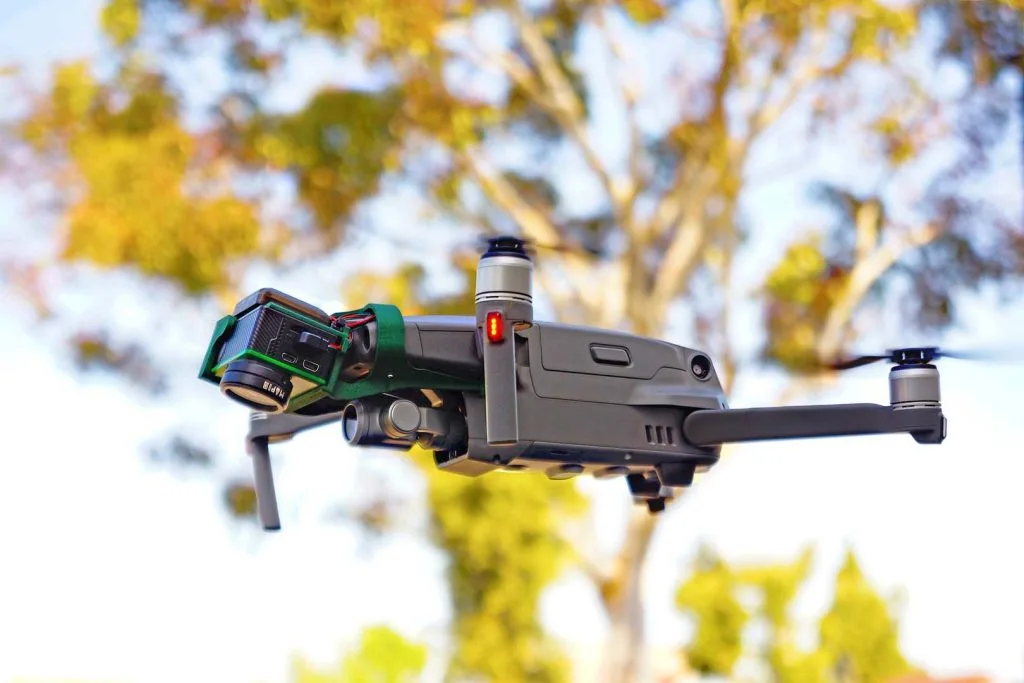
CNC Machined Drone Accessories: A Practical CNC Machining Guide for Lightweight, Repeatable, Production-Ready Hardware
Modern drones are no longer “airframes with propellers.” They are modular platforms, swapping cameras, LiDAR units, RF modules, sprayers, winches, speakers, mapping sensors, and specialized payloads depending on the mission. That modularity is powered by hardware that often looks simple, mounts, rails, clamps, standoffs, adapter rings, electronics enclosures, but must perform like aerospace-grade components: light weight, stiffness where it matters, vibration resistance, reliable threads, repeatable alignment, and surface finishes that don’t sabotage fits.
That is why CNC machined drone accessories have become a core category for manufacturers and integrators who want predictable builds across prototypes, pilot runs, and small-batch production. Compared with printed parts or loosely toleranced sheet-metal brackets, CNC-machined accessories offer:
- Stable datums for alignment-sensitive payloads (cameras, gimbals, antennas)
- Tighter positional tolerances for hole patterns and interface geometry
- Improved stiffness-to-weight with pocketing, ribs, and controlled wall thickness
- Thread durability (including insert options) for frequent service cycles
- Finish compatibility (anodize, hardcoat, conversion coating, passivation)
- Scalable repeatability when you move from one-off prototypes to consistent lots
This long-form guide is written for engineers, product teams, and sourcing managers who want a machining-first view: which CNC processes fit which accessories, how to design for fixturing and inspection, how to specify GD&T without creating quoting chaos, and how to avoid the most common scrap drivers (distortion, coating growth, burrs, thread failures, and ambiguous datums).
If you want to discuss a specific accessory set or request a quote, start here:
Custom CNC UAV Parts Manufacturer
Table of Contents
- What Counts as CNC Machined Drone Accessories (and Why It’s Not Just “Metal Parts”)
- Accessory Types and Their Critical-to-Quality Features (CTQs)
- CNC Process Options: 3-Axis, 3+2, 4-Axis, 5-Axis, and Mill-Turn
- Material Selection: 6061 vs 7075 vs Titanium vs Stainless vs Polymers
- DFM for CNC Machined Drone Accessories: Weight, Vibration, Cable Routing, Serviceability
- Datums, GD&T, and Tolerance Strategy That Actually Works in Production
- Threads, Inserts, Fastener Seats, and Anti-Loosening Interfaces
- Surface Finishes: Type II/III Anodize, Chem Film, Passivation, Bead Blast
- Workholding and Distortion Control for Thin-Wall and Pocketed Accessories
- Inspection Planning: CMM, In-Process Probing, Gauge Concepts, Sampling
- Production Documentation for Drone Accessories: What to Request and When
- Cost Drivers and Quote Inputs: How to Reduce Lead Time Without Downgrading Function
- Detailed Tables (process mapping, finish effects, tolerance recommendations, QC gates)
- Three Real-World Accessory Case Studies
- How JLYPT Supports CNC Machined Drone Accessories from Prototype to Production
- Standards / Metrology Links (DoFollow)
1) What Counts as “CNC Machined Drone Accessories” (Beyond the Obvious)
The phrase CNC machined drone accessories covers any add-on or interface hardware that enables modular payload integration or improves operational robustness. Most accessories fall into one of these functional buckets:
- Payload integration: camera mounts, gimbal interfaces, quick-release plates, damping frames
- Electronics packaging: avionics boxes, RF module housings, GPS mounts, heat spreaders
- Mechanical adaptation: adapter rings, spacers, standoffs, couplers, linkages
- Protection and durability: landing gear blocks, bumpers, guard brackets, skid mounts
- Cable management: clamp blocks, strain relief features, routing brackets
- Field service: alignment tools, assembly fixtures, calibration plates
The difference between a “basic bracket” and a production-grade accessory is usually not complexity, it’s consistency:
- Consistent interface planes (flatness + surface condition)
- Consistent hole position (true position)
- Consistent thread engagement and torque feel
- Consistent fit after finishing (especially anodize growth)
That’s why CNC is so commonly chosen: it can lock these outcomes down with controlled toolpaths, probing, fixturing, and inspection plans.
2) Accessory Types and Critical-to-Quality Features (CTQs)
Table 1 , Common CNC Machined Drone Accessories and Their CTQs
| Accessory category | Typical parts | CTQs (Critical-to-Quality) | Frequent failure if CTQs aren’t controlled |
|---|---|---|---|
| Camera & gimbal integration | camera plates, gimbal yokes, isolation frames | perpendicularity, positional tolerance, symmetry, surface finish | image jitter, gimbal binding, vibration amplification |
| Quick-release payload system | dovetail rails, latch blocks, lock pins | profile/angle control, repeatable datum seat, wear surface hardness | loose payloads, inconsistent alignment, accelerated wear |
| Antenna & GPS mounting | antenna bases, mast clamps, RF module trays | flatness for grounding pads, hole position, thread integrity | intermittent RF performance, loosening, corrosion spots |
| Landing gear and skids | skid blocks, gear adapters, shock plates | impact resistance, fillets, edge breaks, fastener seats | cracking, fretting, difficult field replacement |
| Electronics enclosures | small boxes, lids, heatsinks | sealing groove geometry, flatness, thread quality | moisture ingress, stripped threads, thermal issues |
| Cable routing hardware | clamps, strain-relief blocks | burr-free edges, controlled clamping gap | cable damage, intermittent connectors |
If you design or source CNC machined drone accessories, a useful rule is: CTQs are usually interface features, not outlines. The outer shape can be “pretty,” but the assembly will still fail if datum features drift.
3) CNC Process Options for CNC Machined Drone Accessories
Choosing the machining route is about minimizing setups, protecting datums, and selecting an inspection plan that matches the drawing.
3.1 3-Axis CNC Milling
Best when:
- most features are on one face plus a controlled flip
- the part is prismatic (plates, brackets, simple housings)
- you want the cleanest cost-to-repeatability ratio
3.2 3+2 Positional Machining (Indexing on 5-Axis)
Best when:
- you need multi-face access without true simultaneous tool motion
- the part has angled faces for camera pitch, antenna tilt, or bracket geometry
- you want fewer setups but don’t need sculpted surfacing
3.3 4-Axis Indexing
Best when:
- you need consistent relationships around a perimeter
- you’re machining multiple sides while maintaining a single clamping concept
- you’re producing rails, clamps, or multi-face adapter blocks
3.4 Full 5-Axis Machining
Best when:
- accessory geometry has compound angles or deep access constraints
- you need to hold tight feature-to-feature relationships across multiple faces
- you want to reduce fixture complexity and cumulative stack-up
3.5 CNC Turning / Mill-Turn
Best when:
- accessories include rotational parts: standoffs, spacers, bushings, lock collars
- coaxiality, concentricity, and thread quality matter
- you want to reduce secondary ops and deburr risk
Table 2 , Process Selection Map (Accessory Geometry → Best CNC Route)
| Geometry / requirement | Recommended route | Why it works well for CNC machined drone accessories |
|---|---|---|
| Flat plate with pockets + hole patterns | 3-axis + flip fixture | cost-efficient; stable datums |
| Multi-face block with side holes | 4-axis indexing | fewer re-clamps; better position control |
| Angled camera mount | 3+2 positional | machines angled planes with clean tolerances |
| Complex gimbal interface | 5-axis | maintains relationships across compound faces |
| Standoffs and adapter rings | turning / mill-turn | excellent coaxial control and finish |
4) Material Selection: Strength-to-Weight vs Machinability vs Finish Compatibility
The “right” material depends on load path, vibration environment, corrosion exposure, and whether you need conductive or insulating surfaces.
Table 3 , Materials Commonly Used in CNC Machined Drone Accessories
| Material | Typical accessory uses | CNC machining notes | Finish options | Practical guidance |
|---|---|---|---|---|
| 6061-T6 aluminum | general mounts, trays, housings | very stable; fast cycle times | Type II anodize, chem film | best all-around for cost + machining |
| 7075-T6 aluminum | high-strength brackets, rails, clamps | higher strength; machining still good | Type II/III anodize | excellent for load-bearing accessories |
| Titanium (select grades) | compact high-load parts | slower feeds; tool wear considerations | passivation / special coatings | use when strength + corrosion justify cost |
| 17-4PH stainless | pins, latches, wear parts | good strength; heat-treat impacts | passivation | ideal for latch blocks and lock components |
| 304/316 stainless | corrosion-prone environments | tougher machining than Al | passivation | good for coastal or chemical exposure |
| POM/Delrin, PEEK (program-driven) | isolators, spacers, low-load clamps | chip control varies; thermal creep | usually none | great for vibration isolation and galvanic breaks |
In CNC machined drone accessories, aluminum dominates because it’s lightweight and finish-friendly. But latch components, pins, and wear interfaces often benefit from stainless or hardened strategies.
5) DFM for CNC Machined Drone Accessories: Weight, Vibration, and Serviceability
A strong accessory is not automatically a good accessory. Drone accessories have to survive vibration, frequent payload swaps, and field maintenance, often with limited tooling.
5.1 Weight reduction without creating machining distortion
Pocketing is great until the part becomes a tuning fork. Helpful DFM tactics:
- keep wall thickness reasonably uniform
- avoid extremely thin floors under wide pockets
- add ribs with generous root fillets
- avoid tall, slender cantilevered features unless necessary
- design “fixture-friendly” datum pads for stable clamping
5.2 Vibration-aware design features
- avoid sharp internal corners at stress transitions
- use fillets at bracket roots and around slots
- specify edge breaks (not “break sharp edges” only)
- ensure fastener seats are flat and burr-free
5.3 Serviceability: threads, inserts, and access
Accessories get removed a lot. Consider:
- thread inserts in aluminum for high-cycle removal
- clear tool access for hex keys and torque drivers
- chamfers for easier assembly alignment
- replaceable wear pads if the accessory is a “sacrificial interface”
Table 4 , DFM Checklist for CNC Machined Drone Accessories
| Design element | If you ignore it… | Better DFM decision | Manufacturing payoff |
|---|---|---|---|
| tiny internal radii | small tools, long cycle time | increase radius to standard end mills | shorter lead time, better finish |
| deep pockets with thin floors | warping, chatter | add ribs or thicken floors | higher yield, less scrap |
| undefined cosmetic vs functional surfaces | over-polishing, cost creep | label functional faces and Ra targets | faster quoting, fewer disputes |
| no datum pads | clamp marks, inconsistent setups | add datum bosses/pads | repeatable inspection and assembly |
| “all dimensions tight” | inspection bottleneck | tighten only CTQs | lower cost, same performance |
6) Datums, GD&T, and Tolerance Strategy That Survives Production
Most accessory issues come from drawings that don’t reflect how the part is inspected or assembled. For CNC machined drone accessories, the most productive approach is:
- Identify the mating surfaces (payload seat, rail seat, mounting plane).
- Build the datum scheme around those surfaces.
- Use GD&T to control interfaces, not decoration.
6.1 Practical datum structure (typical)
- Primary datum A: the mounting plane to the drone frame
- Secondary datum B: a long edge, slot, or two-hole pattern controlling rotation
- Tertiary datum C: a perpendicular face or a second hole controlling the final DOF
6.2 Feature controls that matter most
- True position for hole patterns and dowel holes
- Flatness for sealing surfaces or payload seats
- Perpendicularity for camera mounts and connector interfaces
- Profile for dovetail rails or mating wedge geometry
Table 5 , GD&T-to-Function Map for CNC Machined Drone Accessories
| Accessory function | Key feature | Recommended GD&T control | Why it matters |
|---|---|---|---|
| payload repeatability | rail/dovetail profile | profile tolerance | consistent engagement and lock |
| camera alignment | mounting plane and bosses | flatness + position | reduces gimbal trim errors |
| field swap-ability | hole patterns | true position | prevents forced assembly and stress |
| sealing enclosure | lid land + groove | flatness + profile | predictable compression and sealing |
| rotating interface | bore + face | coaxial / perpendicularity | reduces runout and vibration |
For reference concepts in the ISO GPS system (dimensions and tolerances), these are helpful:
7) Threads, Inserts, and Torque-Critical Interfaces
Threads are deceptively expensive when they fail. In CNC machined drone accessories, thread problems usually show up as:
- galling after anodize
- stripped aluminum threads after multiple service cycles
- inconsistent torque feel due to burrs or incomplete threads
- misalignment when fastener seats aren’t flat
7.1 Thread-making options (machining view)
- Rigid tapping: fast, common for aluminum housings
- Thread milling: superior control, great for harder materials or critical threads
- Form tapping: stronger threads in suitable materials; chipless, but needs correct hole size
- Inserts: helicoil or key-lock for high cycle life
7.2 Fastener seating geometry
Spotfaces and counterbores should be treated as functional features:
- keep perpendicularity to the datum plane
- control depth to avoid bottoming
- ensure burr control around edges (especially post-finishing)
Table 6 , Thread Reliability Options for CNC Machined Drone Accessories
| Requirement | Recommended strategy | Notes |
|---|---|---|
| repeated payload swaps | inserts in aluminum | reduces strip risk dramatically |
| tight assembly space | thread milling | easy to tune and verify |
| high vibration | clean seats + controlled engagement | mechanical locking is design-driven |
| post-anodize assembly | specify coating-aware threads | check with go/no-go gauges after finish |
8) Surface Finishes and Their Dimensional Consequences
Finishes are not cosmetic afterthoughts. They affect:
- fit (thickness build)
- electrical conductivity (grounding pads)
- wear resistance (rail engagement, latch blocks)
- corrosion behavior in humid or coastal environments
Common finishes for CNC machined drone accessories:
- Type II anodize (general corrosion protection)
- Type III hard anodize (wear surfaces, rails, clamps)
- Chemical conversion coating (conductivity-friendly corrosion protection)
- Passivation (stainless components)
- Bead blast (appearance and texture; must be controlled)
Table 7 , Finish Planning for CNC Machined Drone Accessories
| Finish | Best for | Dimensional risk | Engineering note |
|---|---|---|---|
| Type II anodize | housings, plates, brackets | medium | define critical fits pre/post finish |
| Type III hard anodize | rails, latch interfaces, wear pads | high | specify coating-aware tolerances |
| chem conversion coat | grounding pads, conductive interfaces | low | good when conductivity matters |
| passivation | stainless pins, latches, hardware | minimal | ensure cleaning + corrosion resistance |
| bead blast | uniform matte surface | variable | can affect sealing surfaces, mask if needed |
9) Workholding, Distortion Control, and Burr Strategy
In CNC machined drone accessories, the scrap drivers are usually not the big features, they’re the “last 5%” problems:
- warped thin plates after pocketing
- burrs that cut cables or prevent mating
- positional shift after a flip setup
- out-of-flat sealing lands after aggressive clamping
9.1 Workholding approaches that improve repeatability
- soft jaws machined to part geometry (repeatable nests)
- dowel-located fixtures referencing functional datums
- controlled clamping zones away from thin walls
- in-process probing to confirm part location before CTQ operations
9.2 Burr control as a design + process requirement
For accessories handling cables and hands, burr control is functional:
- specify edge break requirements (example: “0.2–0.5 mm”) where appropriate
- avoid razor-thin fins by adding chamfers or radii
- consider toolpath directionality near critical edges
Table 8 , Distortion and Burr Mitigation for CNC Machined Drone Accessories
| Problem | Typical cause | Process countermeasure | Design countermeasure |
|---|---|---|---|
| plate warp after pocketing | unbalanced removal | staged rough/semi/finish | ribs, uniform walls |
| chatter on tall walls | tool deflection | constant engagement roughing | reduce wall height or add gussets |
| burrs on cable edges | exit burr from drilling/milling | deburr workflow + inspection | add chamfers/radii |
| hole position drift after flip | datum inconsistency | fixture with repeatable datums | add datum pads/features |
10) Inspection Planning: What “Good” Looks Like for Accessories
Even if you’re not building to a formal aerospace standard, professional inspection practices reduce rework and disputes.
10.1 Tools and methods commonly used
- CMM inspection for true position, perpendicularity, profile
- in-process probing to protect datums and reduce setup error
- thread gauges for functional accept/reject
- surface plate methods for flatness checks
- functional gauges for quick-release rails or latch engagement
NIST is a solid reference for metrology fundamentals:
Table 9 , Inspection Plan Template (Accessory-Focused)
| Feature type | Example accessory feature | Measurement method | Frequency suggestion |
|---|---|---|---|
| hole pattern | payload mount pattern | CMM / optical / probing | 100% early lots; sampling after stability |
| rail profile | dovetail rail | CMM profile + functional gauge | per lot / per setup |
| sealing land | enclosure lid face | surface plate + indicator | per part or sampling by risk |
| threads | M3–M6 accessory threads | go/no-go gauges | 100% where high risk |
| flatness | camera seat plane | CMM or surface plate | per lot; more for thin parts |
11) Production Documentation: What to Request (and When)
For CNC machined drone accessories, documentation needs typically evolve with maturity:
- Prototype stage: dimensional report for CTQs, basic material confirmation
- EVT/DVT: fuller CMM reports, process notes, finish certifications
- Pilot / production: controlled inspection plan, traceability, sampling strategy, change control
Table 10 , Documentation Matrix for CNC Machined Drone Accessories
| Document | Prototype | EVT/DVT | Production |
|---|---|---|---|
| material certificate (by lot) | optional | recommended | often required |
| coating/finish certificate | optional | recommended | required for consistency |
| CMM report (CTQs) | recommended | recommended | sampling / per plan |
| first-article style report | optional | recommended | required when changes occur |
| serialization list | rare | optional | program-dependent |
| packaging and kitting record | optional | recommended | common in production |
12) Cost Drivers and Quote Inputs (Practical, Not Generic)
Cost is dominated by setup time, cycle time, yield loss, and finishing risk. You can reduce cost without lowering performance by making the drawing easier to interpret and inspect.
Table 11 , Cost Drivers in CNC Machined Drone Accessories (and How to Reduce Them)
| Cost driver | Why it increases cost | Better approach |
|---|---|---|
| too many tight tolerances | inspection time + scrap | tighten only CTQs |
| multiple setups | datum stack-up risk + labor | redesign for access; use 4/5-axis strategically |
| hard anodize on tight fits | coating growth causes rework | define post-finish dimensions or mask zones |
| tiny tools from sharp corners | slow feeds + tool break | add internal radii |
| cosmetic finishing everywhere | manual labor | define cosmetic zones only |
RFQ inputs that speed up quoting
- STEP model + 2D drawing with datum scheme
- material + temper/condition
- finish spec and mask requirements
- quantity (proto + forecast)
- CTQ list (what truly matters)
- inspection expectations (CMM, gauges, report format)
13) Detailed Tables (Process Routing, Tolerances, and Finish Impacts)
Table 12 , Example Process Routing: Quick-Release Payload Rail (7075-T6)
| Op | Step | Machine / method | Key controls | Output |
|---|---|---|---|---|
| 10 | saw cut + stock prep | bandsaw | material ID | blank ready |
| 20 | rough mill datums | 3-axis VMC | probe datum A | stable reference |
| 30 | mill rail profile | 4-axis / 3+2 | profile toolpath control | accurate engagement surfaces |
| 40 | drill/ream locating holes | CNC drilling | positional verification | repeatable seating |
| 50 | tap/thread mill fasteners | rigid tap/thread mill | go/no-go gauges | reliable assembly |
| 60 | deburr + edge break | controlled spec | tactile + visual check | safe handling |
| 70 | hard anodize (wear) | finishing | mask critical zones | durable rail surface |
| 80 | final inspection | CMM + functional gauge | CTQ report | shipment-ready |
Table 13 , Tolerance Strategy Guide for CNC Machined Drone Accessories (Practical)
| Feature | Suggested control style | Reason |
|---|---|---|
| payload seat plane | flatness + surface finish Ra | stable alignment and vibration behavior |
| hole patterns | true position to functional datums | ensures interchangeability |
| non-mating outer contours | general tolerances (ISO 2768 style) | reduces cost and inspection load |
| anodized interfaces | define pre/post finish requirement | avoids fit surprises |
| latch engagement geometry | profile tolerance + functional gauge | ensures repeatable locking |
ISO general tolerance concepts (reference):
Table 14 , Finish Effects Checklist (Coating-Aware Planning)
| Finish | Areas to mask (common) | Areas to finish (common) | Risk to manage |
|---|---|---|---|
| Type II anodize | precision bores, grounding pads | general surfaces | thread feel, fit changes |
| Type III anodize | close-fit rails, bearing seats | wear surfaces | thickness growth, rework risk |
| conversion coating | sealing lands , precision fits | grounding interfaces | conductivity targets |
| passivation | N/A (process-based) | all stainless surfaces | cleanliness and handling |
Table 15 , QC Gates for CNC Machined Drone Accessories
| Gate | What’s checked | Why it prevents rework |
|---|---|---|
| after first setup | datums + CTQ baseline | catches setup shift early |
| before finishing | critical fits and positions | prevents coating scrap |
| after finishing | threads + fits + cosmetic zones | ensures assembly readiness |
| final audit | documentation + packaging | avoids shipping errors |
14) Three Case Studies (Accessory-Driven, Production-Realistic)
Case Study 1 , 5-Axis Camera Mount Plate with Vibration-Isolation Geometry (6061-T6)
Accessory goal: hold a camera module square to the airframe while keeping the mounting system lightweight and repeatable.
Key requirements
- stable camera seat plane (flatness-driven)
- positional accuracy on mounting pattern
- chamfered cable pass-through edges
- consistent surface finish for repeatable torque seating
Machining strategy
- 3+2/5-axis positional machining to maintain the relationship between the camera seat and side mounting faces
- finish pass on the seat plane late in the route to minimize handling damage
- controlled edge breaks on cable features to eliminate burr-related wire wear
Inspection approach
- CMM verification of hole true position to datums
- flatness verification of the camera interface plane
- visual/tactile check for cable-safe edges
Result This type of CNC machined drone accessories program often sees immediate improvement in assembly repeatability: fewer shim adjustments, fewer “hand-fit” loops, and more consistent camera alignment between builds.
Case Study 2 , Anodized Quick-Release Payload Rail and Latch Block Set (7075-T6 + Type III)
Accessory goal: allow fast payload swaps with repeatable alignment, minimal play, and wear resistance.
Key requirements
- consistent rail profile and engagement angle
- wear-resistant surfaces (hard anodize)
- hole patterns that match multiple payload plates
- field serviceability without thread degradation
Machining strategy
- rail profile machined with controlled tool engagement to protect surface integrity
- hole patterns machined in a datum-consistent setup to reduce stack-up
- thread strategy designed for repeated service cycles (including insert-ready options)
Finishing and fit planning
- coating-aware tolerance planning to avoid rail tightness after hard anodize
- selective masking (when required) to preserve critical fits
Inspection approach
- CMM profile checks (sampling) plus a functional engagement gauge for speed
- thread gauge checks post-finish
Result For CNC machined drone accessories like rails, the combination of (1) profile control, (2) finish planning, and (3) functional gauging is what separates “nice-looking” rails from truly interchangeable hardware.
Case Study 3 , RF Antenna Mast Clamp + Grounding Base (6061-T6 + Conversion Coat / Anodize Mix)
Accessory goal: mount an antenna module securely while preserving reliable grounding and minimizing loosening under vibration.
Key requirements
- flatness at grounding pads
- controlled fastener seating to keep torque stable
- corrosion management for outdoor exposure
- repeatable assembly datums so the antenna orientation is consistent
Machining strategy
- milling with dedicated datum pads to keep flatness stable
- spotface control around fastener seats
- careful deburr strategy around RF cable routing edges
Finish strategy
- conversion coating where conductivity is needed
- anodize on non-grounding surfaces (design-dependent), with masking to protect pads
Inspection approach
- flatness checks on grounding pads
- positional checks on the mounting pattern
- post-finish verification for masked zones
Result This accessory category highlights a key theme: CNC machined drone accessories frequently require mixed functional surfaces, some for corrosion protection, some for conductivity, and the drawing/finish plan must explicitly support both.
15) Why JLYPT for CNC Machined Drone Accessories (Prototype → Production)
If you’re sourcing CNC machined drone accessories, the fastest path to stable supply is a supplier who can support:
- CNC milling and CNC turning routes matched to accessory geometry
- datum-driven fixturing and repeatable setup control
- finish planning that doesn’t destroy fits (anodize/hardcoat awareness)
- inspection planning that matches GD&T intent (CMM where it adds value)
- scalable workflow from prototypes to small-batch production
JLYPT supports custom UAV and drone machining projects here:
Custom CNC UAV Parts Manufacturer
You can also visit the main site for general capabilities:
JLYPT