
Military UAV Components Manufacturing: A CNC Machining Playbook for Program-Grade Parts, Documentation, and Production Stability
Military-grade UAV platforms operate in an environment where “good enough” becomes expensive fast. A bracket that fits in the lab but loosens under vibration, a housing that distorts after coating, or a thread that galls during depot-level maintenance can turn into weeks of field issues and forced redesigns. In this space, Military UAV components manufacturing isn’t just about making metal parts—it’s about building repeatable processes that protect mission reliability across batches, suppliers, and configuration changes.
This article is a machining-first guide for program managers, mechanical engineers, and sourcing teams who need a practical understanding of how CNC manufacturing decisions affect assembly yield, inspection acceptance, and lifecycle serviceability. It focuses on precision CNC milling, CNC turning, fixturing strategy, GD&T, CMM inspection, coating-aware tolerancing, and documentation such as AS9102 First Article Inspection (FAI)—all within a workflow that scales from prototype builds to low-rate initial production and beyond.
If you’re evaluating a machining partner for UAV hardware, you can review JLYPT’s capability page here:
https://www.jlypt.com/custom-cnc-uav-parts-manufacturer/
Table of Contents
- What “Military UAV Components Manufacturing” Covers (and What It Doesn’t)
- Typical UAV Components and How Machining Choices Change Performance
- CNC Process Architecture: 3-Axis vs 4-Axis vs 5-Axis vs Mill-Turn
- Material Selection for Military UAV Parts (Al, Ti, SS, Ni Alloys, Polymers)
- DFM for UAV Hardware: Weight, Stiffness, Vibration, and Fatigue-Friendly Geometry
- Datums, GD&T, and Stack-Up Control for Multi-Interface Parts
- Threads, Inserts, Fastener Seats, and Torque-Critical Interfaces
- Surface Treatments: Anodize, Hard Anodize, Chem Film, Passivation, Plating
- Workholding, Distortion Control, and Thin-Wall Strategies
- Inspection & Documentation: CMM, Gauge Strategy, AS9102 FAI, Traceability
- Risk Management: Failure Modes in UAV Machined Parts (and Preventative Controls)
- Cost Drivers and Quote Inputs: How to Reduce Scrap Without Diluting Requirements
- Detailed Tables (tolerances, routing, QC checkpoints, finishing impacts, deliverables)
- Three Case Studies from Realistic UAV Component Categories
- How to Engage JLYPT for Military UAV Components Manufacturing
- External Standards Links (DoFollow)
1) What “Military UAV Components Manufacturing” Covers (and What It Doesn’t)
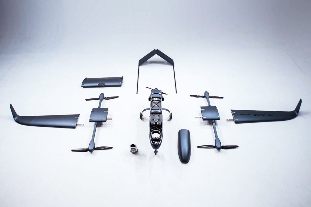
In a defense program context, the phrase Military UAV components manufacturing usually means the controlled production of mechanical hardware used in:
- airframe structures and fittings (brackets, frames, clevises, lugs, clamps)
- payload integration (mounts, housings, gimbal structures, sensor plates)
- avionics packaging (enclosures, trays, heatsinks, connector brackets)
- propulsion and drivetrain interfaces (mount plates, couplers, adapter rings)
- antenna and RF subsystem mounting (precision flatness, positional control)
- ground support and field service hardware (tools, alignment aids, test fixtures)
This guide stays on the manufacturing side—machining processes, inspection, and quality controls. It does not provide instructions for weaponization or harmful payload integration. The objective is robust, auditable production of mechanical components within professional engineering and quality frameworks.
2) Typical UAV Components and How Machining Choices Change Performance
Military UAV platforms combine aerospace-like reliability expectations with rapid iteration and configuration changes. As a result, successful Military UAV components manufacturing is usually built around two principles:
- Interfaces matter more than geometry.
The features that connect parts—bolt patterns, dowel holes, sealing grooves, datum surfaces—drive function and inspection outcomes. - Stability beats peak tolerance.
A production route that holds consistent results (with clear inspection evidence) is more valuable than a one-off “perfect” sample.
Table 1 — Common Military UAV Machined Components and Critical Manufacturing Concerns
| Component category | Typical parts | Primary CTQs (critical-to-quality) | Common failure mode if under-controlled |
|---|---|---|---|
| Payload structures | gimbal housings, sensor mounts, camera plates | positional tolerances, perpendicularity, mass symmetry, surface finish | vibration, misalignment, image jitter, assembly bind |
| Avionics enclosures | CNC-milled boxes, lids, rails, heatsinks | flatness, sealing groove geometry, thread durability, EMI/EMC feature integrity | leaks, loose connectors, thermal hotspots |
| Airframe fittings | brackets, clamps, lugs, linkages | fatigue-friendly radii, hole position, consistent edge breaks | crack initiation, fretting, maintenance difficulty |
| RF/antenna mounts | antenna bases, waveguide supports (program-specific) | flatness, parallelism, controlled finishes, grounding pads | signal loss, intermittent grounding, corrosion |
| Propulsion interfaces | motor mount plates, adapter rings, couplers | concentricity, perpendicularity, thread quality | runout, vibration, bearing wear |
| Service hardware | alignment pins, assembly tools, jigs | gauge repeatability, hardness, wear resistance | assembly variability and rework |

3) CNC Process Architecture for Military UAV Components Manufacturing
Selecting the correct machine architecture is less about “more axes” and more about minimizing setups while protecting datums. In Military UAV components manufacturing, setup count is a direct risk multiplier: every re-clamp introduces a new opportunity for datum shift, distortion, and inspection disagreement.
3.1 3-axis machining (still the workhorse)
Best for:
- prismatic housings with accessible features
- flat plates, brackets, and stiffeners
- parts where all critical features can be machined from one side and a controlled flip
Strengths:
- lower cost per hour
- straightforward programming and inspection correlation
- excellent repeatability with proper probing and fixtures
3.2 4-axis (indexing) and 3+2 (positioning)
Best for:
- multi-face parts needing consistent feature relationships
- connector brackets with side drilling/tapping
- parts with several hole patterns around the perimeter
Strengths:
- improved positional consistency across faces
- often avoids complex 5-axis toolpaths while reducing setups
3.3 5-axis machining
Best for:
- complex housings with compound angles and sculpted pockets
- gimbal structures requiring multi-surface relationships
- weight-optimized components where access is limited
Strengths:
- can keep more features in a single datum coordinate system
- reduces reliance on secondary fixtures
- improves feature-to-feature relationships when used properly
3.4 Mill-turn / Swiss turning for rotational hardware
Best for:
- connector backshells, coupling nuts
- precision spacers, sleeves, bushings
- threaded adapters, sensor collars
Strengths:
- excellent coaxiality and surface finish
- reduces secondary operations
- scalable for larger quantities
Table 2 — Process Selection Map for Military UAV Components Manufacturing
| Part feature profile | Recommended manufacturing route | Key reason |
|---|---|---|
| Prismatic enclosure with internal pockets | 3-axis + dedicated fixture | best cost-to-repeatability |
| Multi-face bracket with side patterns | 4-axis indexing | fewer setups, better position control |
| Gimbal housing with compound faces | 5-axis | preserves datums across complex geometry |
| Connector backshells, threaded collars | CNC turning / mill-turn | concentricity + thread consistency |
| Thin plates with strict flatness | staged milling + stress control | minimizes distortion and rework |
4) Materials Selection for Military UAV Parts
Material choice impacts:
- stiffness-to-weight
- fatigue behavior
- corrosion resistance
- machinability and tool wear
- coating options and dimensional change
- thermal conductivity (critical for electronics packaging)
Table 3 — Material Guide for Military UAV Components Manufacturing (Machining Perspective)
| Material | Where it fits in UAVs | CNC machining behavior | Common finishes | Notes for engineering teams |
|---|---|---|---|---|
| 6061-T6 aluminum | enclosures, general brackets, covers | very machinable, stable | anodize, chem film | cost-effective; good for housings |
| 7075-T6 aluminum | high-strength brackets, load paths | machinable; higher strength | anodize, hard anodize | coating-aware fits important |
| Titanium alloys | compact high-load fittings | slower; heat management required | passivation; specialized coatings | used when strength + corrosion matter |
| 17-4PH stainless | shafts, fastener-like parts, brackets | good; depends on heat treat | passivation | strength and corrosion; magnetic traits vary |
| 316 stainless | corrosive environments | tougher machining | passivation | marine/coastal exposure benefit |
| Nickel alloys (program-dependent) | high-temp/harsh areas | difficult; tool wear | specialized | typically increases cost/time |
| Engineering polymers (PEEK, etc.) | isolators, insulators, non-structural | creep considerations | usually none | great where galvanic isolation needed |
In Military UAV components manufacturing, “best” material is usually the one that holds interface stability under temperature changes, vibration, and service cycles—not necessarily the strongest on paper.
5) DFM for UAV Hardware: Weight, Vibration, and Fatigue-Friendly Geometry
Unlike purely commercial drones, military UAV assemblies often face:
- wider temperature bands
- sustained vibration exposure
- long service intervals
- strict configuration control across revisions
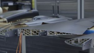
5.1 Lightweighting without inviting distortion
Weight reduction features (deep pockets, thin walls, lattice-like ribs) must be designed with the machining route in mind. A part that’s theoretically stiff can still distort during machining or after coating.
High-value DFM adjustments:
- avoid extremely thin floors under large pockets
- prefer uniform wall thickness where possible
- add radii at internal corners to allow larger tools
- include datum pads or reference bosses for stable workholding
- add “machining land” areas that can be removed later if needed
5.2 Fatigue-friendly geometry
For brackets and load-path hardware:
- use generous fillets at transitions
- avoid sharp notch-like corners near bolted joints
- define edge breaks on all external edges (not “deburr only”)
- avoid “knife edge” rib tips; use rounded profiles
Table 4 — DFM Checklist for Military UAV Components Manufacturing
| Design feature | Risk if ignored | DFM improvement | CNC benefit |
|---|---|---|---|
| Deep pocket + thin wall | chatter, wall push-off | increase wall thickness or add ribs | better finish, less scrap |
| Sharp internal corners | tiny tools, long cycle | add radius consistent with tool | shorter cycle, stronger part |
| No defined datum surfaces | setup variability | add datum pads/bosses | stable inspection correlation |
| Over-specified tolerances | cost and lead time | isolate tight tolerances to CTQs | fewer inspection bottlenecks |
| Thin sealing lands | leak risk | widen sealing surface | reliable assembly |
6) Datums, GD&T, and Stack-Up Control (Program-Grade Expectations)
In Military UAV components manufacturing, inspection disagreements can delay deliveries even when parts “seem fine.” The antidote is a coherent datum scheme and GD&T that matches functional intent.
6.1 Practical datum strategy
A robust approach:
- Primary datum: the mounting plane or interface surface
- Secondary datum: a long edge, slot, or two-hole pattern that locks rotation
- Tertiary datum: a second plane or feature that locks remaining degrees of freedom
6.2 GD&T that commonly matters for UAV components
- Position for hole patterns that drive assembly alignment
- Flatness for sealing surfaces, mating planes, thermal interfaces
- Perpendicularity / parallelism for connector alignment and bracket geometry
- Profile for complex sealing grooves or aerodynamic surfaces (as applicable)
Table 5 — GD&T-to-Function Map (UAV Machined Hardware)
| Function | Feature | Recommended control | Why it matters |
|---|---|---|---|
| Sealed enclosure | lid interface plane | flatness | gasket compression uniformity |
| Connector alignment | connector cutouts | position + perpendicularity | avoids connector stress during mating |
| Structural bracket | bolt pattern | position | prevents assembly preload and distortion |
| Bearing/sensor seat | bore | true position / coaxiality | prevents runout and measurement drift |
| Thermal management | heatsink face | flatness + finish | predictable thermal contact |
For complex assemblies, consider providing a “datum logic note” in the drawing package. It reduces quote risk and prevents “interpretation drift” across suppliers.
7) Threads, Inserts, and Torque-Critical Interfaces
Thread reliability is a frequent pain point because UAV parts see repeated maintenance cycles. In Military UAV components manufacturing, threads are rarely “just holes.”
7.1 Thread strategy options
- Cut tapping (fast, common)
- Form tapping (stronger threads in ductile materials, no chips)
- Thread milling (excellent control, especially in tougher materials or when tolerances are critical)
- Inserts (helicoils, key-lock) for repeated service or weaker base materials
7.2 Fastener seating surfaces
Counterbores, spotfaces, and countersinks need:
- controlled depth and perpendicularity
- burr-free edges
- finish that avoids galling (especially after anodize)
Table 6 — Thread and Fastener Interface Guide
| Interface requirement | Best practice | Manufacturing note |
|---|---|---|
| High service cycles | inserts or thread milling | reduce strip risk and rework |
| Vibration exposure | controlled fit + locking method (design-driven) | keep threads clean post-coating |
| Torque consistency | spotface + flatness control | avoid burr lips around holes |
| Sealing with screws | consistent counterbore geometry | prevents local gasket over-compression |
8) Surface Treatments: Corrosion Control, Wear Resistance, and Coating-Aware Tolerances
Finishes can improve performance—or quietly break assemblies if thickness and masking are not planned.
Common treatments in Military UAV components manufacturing:
- anodize (Type II) for corrosion and appearance
- hard anodize (Type III) for wear surfaces
- chemical conversion coating (chem film) for corrosion control and conductivity
- passivation for stainless parts
- specialized plating (program-dependent)
Coating-aware tolerancing (the non-negotiable detail)
Any finish with measurable thickness can:
- tighten fits in pockets
- alter thread feel
- reduce clearance in connector features
- change electrical grounding behavior
Table 7 — Finish Selection and Dimensional Risk
| Finish | Typical purpose | Dimensional impact risk | Planning actions |
|---|---|---|---|
| Type II anodize | corrosion + cosmetic | medium | define “no-build” zones if needed |
| Type III hard anodize | wear resistance | high | tolerance strategy must account for growth |
| Chem film | corrosion + conductivity | low | good for grounding pads |
| Passivation | stainless corrosion protection | minimal | ensure proper cleaning process |
| Plating (program-specific) | corrosion/wear | variable | tightly define thickness and mask zones |
9) Workholding, Distortion Control, and Thin-Wall Strategies
Machining-induced distortion is often the hidden driver of scrap in Military UAV components manufacturing, especially for:
- thin-walled housings
- large pocketed plates
- long, slender brackets
- parts requiring tight flatness after finishing
9.1 Workholding strategy
High-control methods include:
- custom soft jaws with datum location
- vacuum fixtures for thin plates (application-dependent)
- dedicated nests that support thin walls during finishing
- probing routines to verify part location before critical operations
9.2 Rough/finish sequencing
A stable approach:
- rough pockets leaving uniform stock
- allow stress relief time when required (process-dependent)
- semi-finish to stabilize walls
- finish critical datums last
- machine sealing surfaces in a controlled final pass
Table 8 — Distortion Risks and Mitigations
| Distortion symptom | Typical cause | CNC mitigation | Design mitigation |
|---|---|---|---|
| warped enclosure base | uneven material removal | staged pocketing, balanced toolpaths | add ribs, maintain symmetry |
| sealing surface not flat | clamping pressure + thin walls | support near sealing lands | increase sealing land width |
| hole positions drift after flip | inconsistent datums | machine CTQ pattern in one setup | add datum features |
| thin rib chatter | tool engagement + resonance | constant engagement strategy | increase rib thickness or radius |
10) Inspection & Documentation: CMM, FAI, and Traceability
This is where military-adjacent programs often diverge from hobby or consumer production. Military UAV components manufacturing is frequently judged by the completeness and consistency of its inspection evidence.
10.1 Measurement methods
- CMM for positional tolerances and multi-feature relationships
- height gauge + surface plate for flatness checks
- thread gauges for thread acceptance
- functional gauges to speed up production verification
10.2 First Article Inspection (FAI)
AS9102 FAI is a widely used framework to document that a process can produce parts matching the design definition. Even when a program doesn’t mandate AS9102, adopting a similar structure reduces risk during handoffs and audits.
10.3 Traceability and configuration control
Common expectations include:
- material cert tracking by lot/heat (program dependent)
- revision control (models, drawings, toolpaths)
- serialized parts for lifecycle tracking (where required)
- controlled nonconformance process and corrective actions
Table 9 — Inspection & Documentation Deliverables (Typical)
| Deliverable | What it demonstrates | When it’s most valuable |
|---|---|---|
| CMM report | geometric compliance | complex datums, tight positions |
| AS9102-style FAI | process capability + full feature accountability | first build, revision changes |
| Material certification | material identity and compliance | structural / critical parts |
| Coating cert | finish type and process control | corrosion/wear-critical parts |
| Serialization list | traceability | sustainment and field tracking |
| Control plan / inspection plan | repeatability strategy | scaling from prototype to LRIP |
11) Risk Management: Failure Modes in UAV Machined Parts (and How to Prevent Them)
In Military UAV components manufacturing, the failures that hurt most are not dramatic fractures on day one—they’re subtle reliability degradations that show up after cycles of vibration, temperature changes, and maintenance.
Table 10 — Common Failure Modes and Preventative Controls
| Failure mode | Root cause class | Preventative manufacturing control |
|---|---|---|
| fasteners loosening due to poor seating | machining burrs / inconsistent spotfaces | controlled deburr + spotface inspection |
| corrosion at interfaces | poor finish selection / galvanic coupling | correct coating + masking + isolation strategy |
| connector misalignment | datum drift across setups | single-setup machining of patterns + CMM verification |
| thread strip during maintenance | weak threads / coating build-up | inserts + thread process control + post-finish thread check |
| leakage in enclosure | flatness variation / groove error | control flatness + profile of grooves + gasket land finish |
12) Cost Drivers in Military UAV Components Manufacturing (and How to Quote Smarter)
Cost often escalates due to preventable ambiguities:
- unclear CTQs (everything “tight”)
- undefined cosmetic vs functional surfaces
- finish thickness not considered in fits
- frequent revision changes without configuration control
- complex parts designed without a stable datum plan
Table 11 — Cost Drivers and Practical Reductions (Without Compromising Intent)
| Cost driver | Why it increases cost | Smarter alternative |
|---|---|---|
| too many setups | more labor + higher error risk | redesign for tool access; add datum pads |
| tiny internal radii | requires small tools, slow feeds | increase radii to match standard end mills |
| blanket tight tolerances | more scrap + more inspection time | tighten only CTQs; loosen cosmetic dims |
| complex masking | adds manual ops | group critical surfaces; design coating reliefs |
| post-finish rework | delays and surface damage | plan coating-aware tolerances upfront |
13) Detailed Tables for Program Planning (Manufacturing, QC, and Finishing)
Table 12 — Example Process Routing: CNC-Milled Avionics Enclosure (Aluminum)
| Op # | Step | Machine/Method | In-process controls | Output |
|---|---|---|---|---|
| 10 | Rough mill external + internal cavities | 3-axis VMC | probing + stock allowance | stable rough blank |
| 20 | Semi-finish pockets and walls | same setup | wall thickness checks | reduced distortion |
| 30 | Machine sealing grooves + gasket lands | finishing toolpath | surface finish control | sealing geometry |
| 40 | Drill/tap mounting patterns | rigid tapping / thread milling | thread gauge checks | assembly-ready threads |
| 50 | Flip and finish mounting base | fixture referencing datums | flatness monitoring | final datum plane |
| 60 | Deburr + edge break | defined standard | visual + tactile acceptance | wire-safe edges |
| 70 | Finish: anodize/chem film | controlled vendor process | mask critical zones | corrosion protection |
| 80 | Final inspection + documentation | CMM + gauges | AS9102-style FAI (as required) | release package |
Table 13 — Tolerance Planning Guide (Conceptual, Program-Dependent)
| Feature class | Recommended approach | Why |
|---|---|---|
| interface planes | specify flatness/parallelism | prevents assembly distortion and leakage |
| hole patterns | specify position to datums | controls fit and reduces assembly stress |
| non-functional outlines | general tolerances | reduces cost and inspection burden |
| coated fits | define pre/post finish condition | prevents fit surprises |
| threads | define class + acceptance method | improves service reliability |
(Exact numeric tolerances should be set by your design intent, load cases, and interface requirements. The key is to connect tolerance to function and inspection method.)
Table 14 — Tooling and Toolpath Practices That Improve Repeatability
| Feature type | Preferred strategy | Benefit in production |
|---|---|---|
| deep pockets | constant engagement roughing | less chatter, predictable deflection |
| thin walls | semi-finish stabilization then finish | less spring-back variation |
| sealing lands | single controlled finish pass | consistent flatness/finish |
| critical holes | drill + ream where needed | stable size and position |
| threads | thread milling for critical features | better control, easier rework |
Table 15 — Quality Gate Checklist for Military UAV Components Manufacturing
| Gate | What to verify | Typical tools |
|---|---|---|
| incoming material | ID, condition, cert match | receiving inspection |
| in-process machining | datums, critical dimensions | probing, micrometers |
| pre-finish inspection | CTQs before coating | CMM/fixtures |
| post-finish verification | fit-critical dimensions, masking success | thickness gauge, CMM sampling |
| final release | documentation completeness | FAI pack, inspection report |
14) Three Case Studies (Program-Realistic Categories)
These examples reflect the kinds of parts where machining discipline and documentation make the difference in Military UAV components manufacturing—especially when a program transitions from prototypes to controlled production.
Case Study 1 — 5-Axis EO/IR Payload Gimbal Housing (Aluminum + Coating-Aware Fits)
Part type: multi-surface housing with compound angles, weight-optimized pockets, and multi-interface mounting points
Primary risks: datum shift, thin-wall distortion, coating-related fit issues
Manufacturing strategy
- 5-axis machining to maintain feature relationships in a unified coordinate system
- roughing that preserved wall symmetry (balanced material removal)
- finishing critical bearing/seat features late in the routing
- controlled deburring at cable paths and connector windows
Inspection approach
- CMM mapping of position and perpendicularity across multiple faces
- targeted surface finish checks at interface planes
- AS9102-style feature accountability for the first production unit(s)
Why it matters Payload housings often expose tolerance stack-ups quickly. A stable machining route reduces rework loops and protects alignment through finishing and assembly.
Case Study 2 — Avionics Enclosure with Sealing and Thermal Interface Requirements (6061-T6)
Part type: CNC-milled box + lid with gasket groove, mounting rails, and connector apertures
Primary risks: leakage due to flatness/groove variation, inconsistent threads after finishing, uneven thermal contact
Manufacturing strategy
- defined primary datum on the mounting base to control enclosure alignment
- final-machined sealing land in a controlled finishing pass
- thread strategy chosen to maintain durability across maintenance cycles (process-dependent)
- finish planning that preserved conductive/grounding interfaces where required by design
Inspection approach
- flatness verification on sealing lands
- functional checks using a controlled lid fit method
- post-finish sampling for fit-critical features
Why it matters A box that “looks right” can still fail in service if sealing geometry and interface planes drift. This is a classic Military UAV components manufacturing trap—and also a classic place where disciplined CNC planning pays off.
Case Study 3 — Structural Bracket Set for Airframe Integration (7075-T6 + Hard Anodize Wear Zones)
Part type: bracket family with multiple variants, shared datums, and repeated assembly cycles
Primary risks: fatigue initiation at sharp transitions, hole position variability across variants, wear at clamping interfaces
Manufacturing strategy
- standardized datum scheme across the bracket family for interchangeability
- fillet and edge break controls treated as functional features, not cosmetic details
- wear surfaces finished with hard anodize where appropriate, with coating-aware tolerance planning
Inspection approach
- gauge strategy for fast verification of repeated hole patterns
- CMM sampling plan tied to variant family risk
- documented revision control to prevent mixed configurations
Why it matters Structural bracket families often expand over time (new payloads, new antennas, new routing). A consistent manufacturing + inspection template reduces configuration risk as the program evolves.
15) How to Engage JLYPT for Military UAV Components Manufacturing
For CNC-machined UAV hardware, success typically comes from aligning early on:
- what features are CTQ
- what surfaces are functional vs cosmetic
- what finish is required (and where masking is needed)
- what documentation is expected (inspection reports, FAI format, traceability level)
JLYPT provides CNC machining services for UAV components—from precision milled housings and brackets to turned spacers and interface hardware—supporting prototype-to-production workflows.
Start here (internal link required):
https://www.jlypt.com/custom-cnc-uav-parts-manufacturer/
Additional internal link:
https://www.jlypt.com/
RFQ Checklist (Recommended for Accurate Lead Time and Pricing)
- 3D model (STEP preferred) + 2D drawing with GD&T and datums
- material specification and temper/condition
- finish specification, including any mask/no-coat zones
- quantity (prototype, LRIP, and estimated annual volume)
- inspection expectations (CMM report, FAI format, sampling plan)
- packaging requirements (scratch protection, kitting, labeling, serialization)
- revision/configuration notes (baseline rev, planned changes)
This is the shortest path to stable, repeatable Military UAV components manufacturing—and the fastest way to avoid late surprises when a program scales.


