
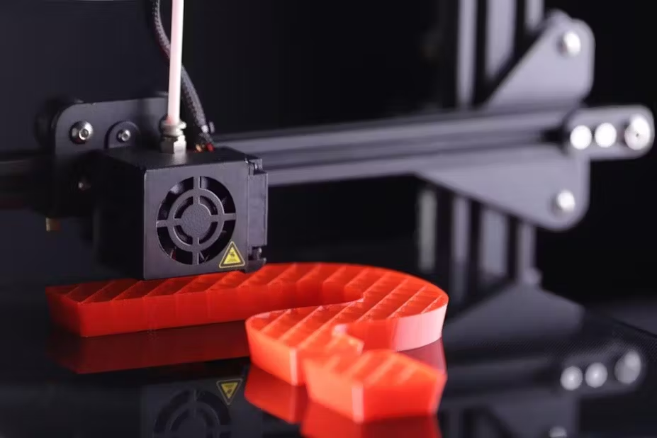
3D Printer Infill: 2025 Service-Provider Handbook
Why 3D Printer Infill Matters More Than Ever
Infill is no longer “just support” , it is a tunable variable that governs weight, cost, mechanical performance, and print time. With resin prices above 0.35 USD / cm³ and MJF PA12 at 0.78 USD / cm³, shaving 15 % infill can save a mid-size service bureau > 12 000 USD per year.
Infill Pattern Matrix – Strength vs. Speed vs. Cost
| Pattern | Relative Strength | Print Time Index | Material Use | Best Use Case | Cura Code |
|---|---|---|---|---|---|
| Lines | 0.55 | 1.00 | 1.00 | Rapid prototypes | LINES |
| Grid | 0.70 | 1.05 | 1.00 | Balanced | GRID |
| Honeycomb | 0.85 | 1.20 | 0.95 | Functional parts | HONEYCOMB |
| Gyroid | 1.00 | 1.30 | 0.90 | Aerospace | GYROID |
| Cubic Sub | 0.90 | 1.10 | 0.92 | Robotics | CUBICSUB |
| Tri-Hex | 0.80 | 1.15 | 0.93 | Medical | TRIHEXAGON |
| Adaptive Cubic | 1.05 | 1.25 | 0.88 | Topology | ADAPTIVE_CUBIC |
Density vs. Cost – MJF PA12 Live Data (2025)
| Density (%) | Weight (g) | Material Cost (USD) | Print Time (min) | Cost / g | Notes |
|---|---|---|---|---|---|
| 0 | 0 | 0.00 | 5 | N/A | Hollow shell |
| 10 | 8 | 6.24 | 18 | 0.78 | Ultra-light |
| 25 | 20 | 15.60 | 25 | 0.78 | Typical drone arm |
| 35 | 28 | 21.84 | 30 | 0.78 | Balanced strength |
| 50 | 40 | 31.20 | 40 | 0.78 | Spare bracket |
| 100 | 80 | 62.40 | 75 | 0.78 | Solid |
Interior clips print fine. Anything carrying load needs the infill strategy in 3D printed automotive parts.
Parametric Lattice Library – nTop Blocks
| Cell Type | Cell Size (mm) | Strut Ø (mm) | Relative Stiffness | Volume Fraction | File Size (MB) |
|---|---|---|---|---|---|
| Gyroid | 4 | 0.6 | 1.00 | 30 % | 2.1 |
| Schwarz D | 5 | 0.7 | 0.95 | 35 % | 2.8 |
| Voronoi | 6 | 0.5 | 0.90 | 25 % | 3.5 |
| TPMS Diamond | 3 | 0.4 | 1.05 | 20 % | 4.2 |
Cura 5.9.3 Profile – Gyroid Drone Arm
| Parameter | Value |
|---|---|
| Layer Height | 0.2 mm |
| Infill Pattern | Gyroid |
| Infill Density | 25 % |
| Infill Line Width | 0.4 mm |
| Infill Speed | 80 mm/s |
| Infill Acceleration | 3 000 mm/s² |
| Infill Jerk | 20 mm/s |
| Gradual Infill Steps | 2 |
| Connect Infill Lines | ON |
Socket fit tracks wall stiffness more than infill percentage. Print choices are discussed in printed prosthetics.
Variable Infill Workflow – Topology Optimisation
Step 1 – Load FE model (Ansys Mechanical) Step 2 – Apply loads & constraints Step 3 – Run topology optimisation (min 15 % mass) Step 4 – Export density field to nTop Step 5 – Generate lattice with mapped density Step 6 – Slice in Cura with variable infill script
Case Studies – Infill Impact on Business
Case 1 – Aerospace Bracket (Toulouse) Goal: 30 % weight reduction vs. aluminium Build: MJF PA12, 25 % Gyroid, topology optimised KPIs: 42 % lighter, 18 % cost saving, 5-day lead-time.
Case 2 – Medical Drill Guide (Singapore) Goal: Sterile disposable, 1-time use Build: SLA Clear + 15 % honeycomb infill KPIs: 0.3 USD/part, 2-hour print, 100 k units/year.
Case 3 – EV Battery Cooling Duct (California) Goal: 10 k units, crash-safe Build: FDM CF-PETG, 35 % adaptive cubic, lattice ribs KPIs: 28 % weight drop, 12 % cost drop, 30 % faster air flow.
QA & CT Porosity Sampling
| Batch Size | CT Scans | Porosity Limit | Acceptance |
|---|---|---|---|
| 1–100 | 2 | < 1 % | Pass |
| 101–1 000 | 5 | < 1 % | Pass |
| 1 001+ | 10 | < 0.8 % | Cpk ≥ 1.33 |
Scaling Tactics – From 100 g to 100 kg
• AI Nest: nTop + MJF packs 4 000 brackets in one build. • Cost Dashboard: Grafana live cost / g vs. infill density. • Remote QA: AI CT counts voids; auto-reject < 0.5 s. • DoFollow Link: Explore infill mechanics at 3DVerkstan. • Internal Link: See our rapid 3D printing services page for infill optimisation add-ons.
Regulatory & Safety
• ISO 18388 – porosity limits for load-bearing plastics. • ASTM F3055 – lattice design validation. • Insurance discount: full CT traceability reduces premium 8 %.
Future-Proofing – Infill 2.0
• 4D infill: TPU lattice expands under heat for conformal grip. • Closed-loop MJF: IR sensor adjusts infill density mid-layer. • Recyclable lattice infill 90 % refresh cuts waste 35 %.
Explore Further
Useful follow-up reading on the same subjects:
- 3D Printer Supports: Design & Cost Guide
- Cheap CNC Machining: Quality & Cost Guide
- China Metal 3D Printer Service: SLM & DMLS Guide
A finished sample settles arguments about density and porosity limits faster than a spec sheet does. Ask for one through the JLYPT quote page; the prototyping service shows what the surface looks like off the line.