MIL-A-8625 Type III Hard Anodize: A Practical Guide for Wear-Critical CNC Parts
Specifying “hard anodize per MIL-A-8625 Type III” without a thickness, a class, and a plan for dimensional growth is how wear-critical parts come back oversized or with chipped edges. The coating is one of the hardest finishes available to an aluminum part, but it is also one of the least forgiving. This guide covers the decisions that have to be made before the drawing is released: when Type III beats Type II, what thickness and hardness are realistic, how much the part grows, which alloys cooperate, and what to put on the print so the finish arrives repeatable. If you already have a part that sees sliding contact and need a shop that machines and finishes under one roof, send the drawing through the JLYPT quote form and the tolerancing gets checked before metal is cut.
This is written for the people who own the callout: design engineers putting a wear surface on an aluminum housing, buyers comparing a hardcoat quote against a plating quote, and quality engineers writing an inspection plan against a specification that leaves several choices open. Type II anodize is covered separately in our guide to MIL-A-8625 Type II anodize. This guide assumes you have already decided the part needs the harder coating and focuses on getting Type III right.
What Type III actually is, in manufacturing terms
Type III is a sulfuric acid anodize run cold and hard. The bath is held near 0 degrees C (32 degrees F), far colder than the ambient Type II bath, and the part is driven at a higher current density for longer. The cold temperature slows the acid from dissolving the oxide as it grows. The result is an aluminum oxide layer that is thicker, denser, and substantially harder than conventional anodize. It is the oxide of the part itself, grown out of the substrate, not a coating laid on top, which is why it cannot flake the way a applied layer can but also why it changes dimensions.
One point that separates a good hardcoat supplier from a poor one is temperature control. The bath near 0 °C has to be held there under production load, not just at startup, because a warm bath dissolves the oxide faster than it grows and the coating comes out soft. That is why hardcoat tanks are smaller and slower than conventional anodize lines: the chilling and power demand set the pace, and lead times of five to ten business days are normal.
The specification that governs it is MIL-A-8625, currently revision F. That single document covers several types of anodic coating: chromic acid types, conventional sulfuric (Type II), and hardcoat (Type III). When a drawing says only “anodize per MIL-A-8625” it has not actually said which coating to produce. Type III must be named explicitly, along with the class, or the shop has to ask. The same specification also defines two classes: Class 1 is undyed, and Class 2 is dyed, in practice black. There is no bright color option under Type III, because the natural oxide is gray to bronze and darkens as it thickens.
Hardcoat goes by many names in RFQs and catalogs: Type III, hard anodize, hardcoat, engineering anodize, and the aerospace designation AMS 2469. ISO 10074 covers much the same ground in international drawings. If a customer calls out one of these equivalents, confirm the governing document and the required thickness before quoting, because the acceptance criteria are not identical across them.
When Type III is the right call, and when it is not
The reason to specify Type III is wear. If a surface sees sliding contact, abrasive media, repeated mechanical engagement, or needs to resist galling under load, the extra hardness earns its cost. Typical candidates are pistons, valve bodies, cylinder bores, gears, actuator components, fixtures, and tooling that rubs against other parts. Electrical insulation is a secondary benefit: the thick oxide is a strong dielectric where a grounding path is not wanted.
It is the wrong call when the requirement is really corrosion protection or appearance. A bracket or housing that never rubs does not need the hardness, and the thicker, darker, rougher coating adds cost, lead time, and dimensional risk for no functional gain. When the surface must stay electrically conductive, an anodic coating is the wrong family entirely, and a chemical conversion coating is the correct choice; our guide to MIL-DTL-5541 Class 3 conductive chem film covers that case. When a legacy drawing still cites the superseded designation, the mapping is explained in MIL-C-5541 vs MIL-DTL-5541.
There is one more reason to pause before upgrading: fatigue. The hard oxide is brittle and can initiate cracks, which lowers fatigue strength, most noticeably on 7075 and 2024. On a part that sees cyclic loading, specify the thinnest coating that meets the wear need, and ask about shot peening before anodizing. A wear surface on a fatigue-critical component is an engineering tradeoff, not a default.
Thickness and hardness: realistic numbers, not catalog dreams
| Attribute | Type II (sulfuric) | Type III (hardcoat) |
|---|---|---|
| Bath temperature | Ambient, roughly 20–25 °C | Cold, near 0 °C (32 °F) |
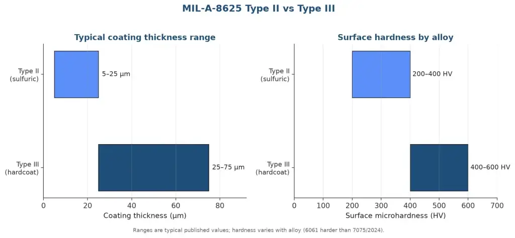
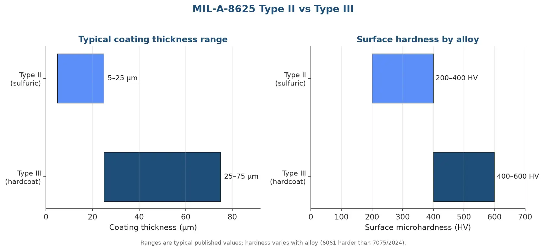
| Typical thickness | 5–25 µm (0.0002–0.001 in) | 25–75 µm (0.001–0.003 in), 50 µm nominal |
| Surface hardness | 200–400 HV | 400–600 HV, alloy dependent |
| Primary role | Corrosion, color, appearance | Wear, abrasion, sliding contact |
| Color options | Full dye range | Natural gray-bronze or black only |
| Dimensional growth | Minor, often ignored | ≈50% outward, must be planned |
| Edge sensitivity | Low | High; radius edges to ≥0.25 mm |
| Fatigue effect | Minor | Reduces fatigue strength; review cyclic parts |
| Governing spec | MIL-A-8625 Type II | MIL-A-8625 Type III, AMS 2469, ISO 10074 |
Published practice puts Type III thickness in the 25 to 75 micrometer range (0.001 to 0.003 inch), with 50 micrometers (0.002 inch) the usual nominal default when the drawing does not state one. Thicker builds are possible on 6061, but hardness tends to fall as thickness climbs. Surface microhardness lands around 400 to 600 HV depending on alloy, often quoted as roughly 60 to 70 HRC equivalent, which puts it in the territory of hardened steel for a scratch test. Type II, by comparison, sits at 5 to 25 micrometers and 200 to 400 HV.
Two cautions about these numbers. First, they are typical ranges, not guarantees for every alloy; a copper bearing 2024 or a silicon rich casting will not reach the top of the hardness band. Second, MIL-A-8625 specifies abrasion resistance and thickness by agreement rather than a single universal figure, so the drawing needs to name the value it expects. “Hard anodize per MIL-A-8625 Type III, 50 µm nominal” is a usable callout. “Hard anodize” alone is not.
Dimensional growth: the part gets bigger, plan for it
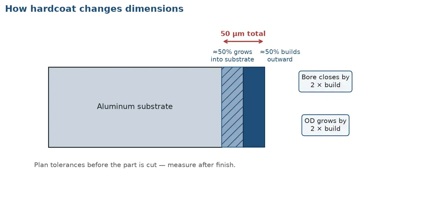
An anodic coating grows in both directions. About half of the thickness consumes the substrate and about half builds outward, so a 50 micrometer coat adds roughly 25 micrometers (0.001 inch) on each face. On an external diameter the part grows by twice the per-face build. On an internal bore the opening closes by twice the build. Threads are the classic trap: on a 60 degree thread the pitch diameter changes by roughly four times the per-face build, which can seize a mating part if the thread was cut to final size before coating.
The practical rules are straightforward. Machine critical diameters undersize or oversize by the expected build, leave a grinding or lapping allowance where a tight fit must be held after coating, and mask threads and grounding faces. Sharp external corners are a problem because the oxide grows toward a point and chips or burns; break edges to a radius of at least 0.25 mm (0.010 inch) before finishing. And remember that the coating is rougher than the base metal: an 0.8 µm Ra machined surface often comes back around 1.5 to 2 µm Ra, so a seal or bearing surface may need post-coat finishing.
Alloy choice: which grades cooperate
Not all aluminum hardcoats equally. The 6061 and 6063 grades and the 5xxx family produce the hardest, most uniform coatings and are the safest choice when a part is designed around hardcoat. The aerospace workhorse 7075 and the copper rich 2024 still get hardcoated regularly, but the coating comes out darker, softer, more porous, and more prone to burning at thin edges. Cast alloys with high silicon content are the most difficult, with rough, soft coatings.
What this means at the drawing stage: if the part can be made from 6061 without giving up required strength, hardcoat performance will be more predictable. If the design requires 7075 or 2024, tell the finishing house the grade up front and agree on a thickness that the alloy can actually hold. A 75 micrometer callout on a high copper alloy is a recipe for soft spots and color variation, not a harder part.
Class 1, Class 2, and the truth about color
Under MIL-A-8625, Class 1 is the uncoated-as-dyed condition, more simply the natural finish. On Type III it comes out gray to dark bronze, and it darkens as the coating thickens and varies with alloy. Class 2 is dyed, and in hardcoat practice that means black. A black hardcoat is common and dyes well because the base oxide is already dark.
Bright colors are not available. If a program needs red, blue, or gold color coding, that is a Type II job, where the thinner, clearer sulfuric coating accepts a full dye range. Trying to pull a bright color out of hardcoat produces a muddy result and wastes the hardness that justified the process in the first place. If appearance matters more than wear, choose Type II and accept the softer coating.
Sealing, PTFE, and the wear-versus-corrosion tradeoff
The as-grown hardcoat is porous, and what happens to those pores is a decision. Leaving the coating unsealed preserves maximum hardness and wear resistance, which is what a sliding surface wants. Hot water or nickel acetate sealing closes the pores and improves corrosion resistance, at some cost to surface hardness. For a part that both wears and corrodes, the sealing choice has to balance the two, and the drawing should say which matters more.
A third option is PTFE impregnation, where a fluoropolymer is worked into the pores to create a dry-lubricated surface with a friction coefficient around 0.1 to 0.2. This is useful on sliding pairs that cannot be oiled, but it adds cost and lead time and changes the surface slightly. Specify it only when the low-friction behavior is actually required.
Inspection and acceptance: what “good” looks like on paper
A hardcoat lot is normally accepted on thickness, appearance, and abrasion resistance, with corrosion performance added when sealing is specified. Thickness is measured by a nondestructive eddy-current gauge on a sacrificial area or a companion coupon, since measuring the part itself may not be possible on a finished surface. Abrasion resistance under MIL-A-8625 is evaluated by a Taber test on representative panels rather than on the part. Because hardness is alloy dependent, a hardness number without a named alloy is not a meaningful acceptance criterion.
For receiving inspection, ask the supplier for a coating thickness report, the alloy and process used, and any sealing or impregnation step. Define cosmetic zones if the part has a visible face, since hardcoat appearance varies even on a well-run line. Where a fit is critical, a first-article dimensional report before and after coating is worth far more than a generic certificate.
Defects and their real causes
Burning at edges. High current density concentrates at sharp corners and thin sections, overheating the coating and leaving a burnt, powdery area. The fix is geometric: radius edges before finishing and use a contact and racking layout that distributes current.
Soft or chalky coating. Usually a bath temperature that ran warm, a copper or silicon rich alloy pushed beyond what it can hold, or a coating grown too thick. Confirm the alloy, tighten temperature control, and reduce the target thickness.
Color variation between parts. Normal on high alloy grades, worse when parts come from different alloy lots or see different surface preparation. Hold the alloy and surface finish consistent, and use a control sample if appearance must match.
Chipped coating on corners and threads. The oxide is brittle. Unradiused edges and uncoated-mask transitions are the usual sites. Radius edges, mask deliberately, and avoid post-coat bending.
CNC machining decisions that affect the final finish
Hardcoat exposes machining decisions that other finishes hide. Every part needs a firm electrical contact, so the racking point has to exist on the raw part and will leave a small mark; place it on a nonfunctional surface. Tool marks and heavy burrs carry through the coating and even amplify, so deburr before finishing and keep a consistent surface finish. Coolant residue and embedded iron from tooling cause spots in the coating, so parts must be clean before they reach the tank.
Above all, build the coating growth into the CAM plan. A shop that machines a bore to final size and then sends it for 50 micrometers of hardcoat will get a bore that is too small. The machining and finishing steps have to be planned together, which is the reason to route a hardcoat part to a supplier that handles both. Our custom aluminum anodizing services page describes how machining and finishing are integrated.
Standards and reference documents
- MIL-A-8625F — the governing US specification for anodic coatings, covering Type III hardcoat and its classes.
- AMS 2469 — aerospace hard anodic coating specification, commonly called out on aircraft components.
- ISO 10074 — international specification for hard anodic oxidation coatings on aluminum.
- ASTM B117 — neutral salt spray test, used when corrosion performance is specified alongside wear.
RFQ checklist: send this to get an accurate quote
A hardcoat quote cannot be accurate without a few specific answers. Include them in the first email and the back-and-forth drops sharply:
- The alloy and temper, for example 6061-T6 or 7075-T6.
- The governing callout: MIL-A-8625 Type III, plus class (1 natural or 2 black).
- Target thickness in micrometers or inches, and which surfaces it applies to.
- Critical fits and tolerances, with a note on whether growth must be compensated or masked.
- Any threads, bores, or grounding surfaces that must be masked.
- Whether the priority is wear, corrosion, or both, and the sealing or PTFE preference.
- Quantity, and whether a first-article dimensional report is required.
Making a Type III order predictable
A successful Type III program comes down to four things named before the part is cut: the thickness, the class, the plan for dimensional growth, and the alloy. Get those right and hardcoat becomes a controlled process instead of a source of oversized parts and chipped edges. If you have a wear-critical aluminum part and want a supplier that machines and finishes it under one roof, route the drawing and requirements through the JLYPT quote form.