Anodizing Thickness Tolerance Impact: What Engineers and Buyers Must Know Before Releasing CNC Aluminum Parts
When an aluminum part fails after anodizing, the root cause is often not the alloy, not the machining program, and not even the anodizing chemistry alone. In many production failures, the issue is thickness tolerance.
A part may pass inspection before surface treatment and still become unusable after anodizing because the coating buildup changes the effective dimension of bores, threads, sealing lands, bearing fits, electrical contact zones, and sliding surfaces. In procurement terms, that means scrap, delayed assembly, supplier disputes, and cost escalation. In engineering terms, it means the dimensional tolerance strategy was incomplete.
For CNC machined aluminum components, anodizing thickness is not a cosmetic afterthought. It is a controlled conversion coating with direct influence on dimensional tolerance, corrosion resistance, dielectric behavior, wear resistance, sealing response, and downstream assembly performance. The thicker the anodic film, the greater the impact on final part geometry, especially on precision features.
This is why engineers specifying anodized parts must align the machining tolerance, alloy selection, anodizing type, coating thickness, masking strategy, and inspection plan before production begins.
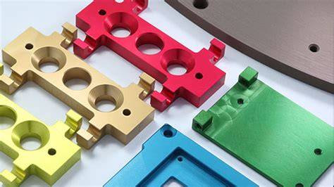
At JLYPT, this issue comes up frequently in RFQs for aerospace brackets, medical device housings, precision enclosures, and automotive machined parts. Customers ask for hard anodizing, tight tolerances, threaded features, sealing grooves, and cosmetic consistency in the same part. These requirements can coexist, but only when anodizing thickness tolerance is engineered into the process window from the start.
If you are sourcing tight-tolerance aluminum parts and need production support on machining plus surface finishing, JLYPT provides integrated CNC manufacturing and anodizing support here: Custom Aluminum Anodizing Services
Why Anodizing Thickness Tolerance Matters
Anodizing is an electrochemical conversion process that transforms the aluminum surface into aluminum oxide. Unlike paint or plating, anodizing is partly penetrative and partly additive. A portion of the oxide layer grows outward from the original surface, and a portion penetrates inward into the substrate.
That growth behavior is the reason thickness tolerance matters so much.
Even when the specified coating thickness looks small on paper, the actual dimensional effect on a close-fit feature can be critical. A bore diameter can shrink. An external diameter can grow. A thread can tighten or seize. A slot width can narrow. A sealing face can move outside flatness or height tolerance. In electrical applications, increasing oxide thickness can improve dielectric resistance while making grounding impossible at selected points unless masked.
For B2B buyers, thickness tolerance affects six core business outcomes:
- final assembly pass rate
- interchangeability across production batches
- functional performance in wear and insulation environments
- cosmetic consistency
- compliance with customer or military standards
- total production cost
In short, anodizing thickness is not just a finishing parameter. It is a product design variable.
What Standards Govern Anodizing Thickness
The most commonly referenced standard in industrial procurement is MIL-A-8625, now commonly cited in practice through its anodic coating classifications for aluminum and aluminum alloys. Buyers, machinists, and finishers also refer to ISO specifications and customer-specific drawings. For North American manufacturing environments, MIL-A-8625 terminology remains deeply embedded in print requirements, quality plans, and supplier communication.
Common anodizing categories used in production
| Anodizing Type | Typical Description | Common Thickness Range | Functional Priority | Typical Appearance |
|---|---|---|---|---|
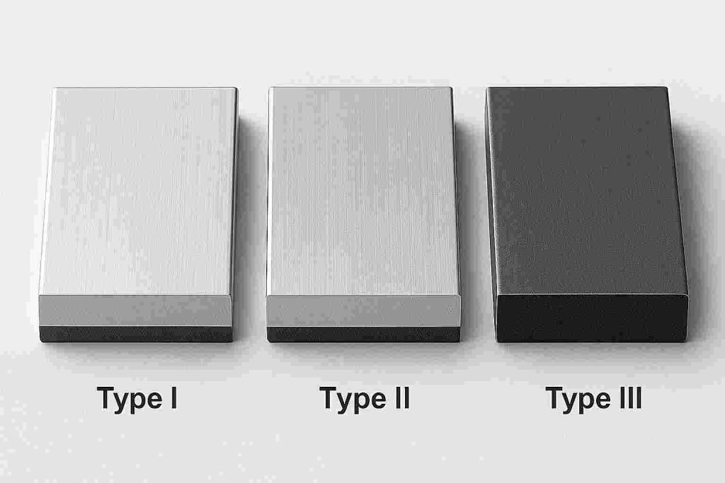
| Type I | Chromic acid anodizing | Thin, usually lower than sulfuric anodize | Corrosion protection, minimal dimensional impact | Gray to light metallic |
| Type II | Sulfuric acid anodizing | Moderate thickness | Corrosion resistance, cosmetic finish, moderate wear resistance | Clear, black, dyed colors |
| Type III | Hard anodizing / hardcoat anodizing | Thick coating | High wear resistance, higher hardness, dielectric strength | Dark gray, bronze, blackish |
| PTFE-sealed hard anodize | Type III with low-friction enhancement | Similar to Type III | Wear plus friction reduction | Dark matte |
| Clear anodize service | Usually Type II Class 1 clear | Moderate thickness | Corrosion resistance and clean metallic appearance | Transparent to slightly satin |
Common classification language engineers use
| Specification Element | Meaning |
|---|---|
| Type II | Sulfuric acid anodizing |
| Type III | Hard anodizing / hardcoat |
| Class 1 | Non-dyed, natural/clear finish |
| Class 2 | Dyed finish |
| Sealed | Pores closed for better corrosion resistance |
| Unsealed | Better for adhesive bonding in some cases, reduced corrosion protection |
| Thickness callout | Coating thickness requirement, often in µm or mil |
| Masking requirement | Areas excluded from anodizing for tolerance, conductivity, or fit |
Typical Anodizing Thickness Ranges
The actual range depends on alloy, process chemistry, bath temperature, current density, fixturing, surface finish, geometry, and customer specification. Still, the following ranges are practical reference values used in industry.
Table: Typical anodizing thickness ranges by process
| Process | Typical Thickness (µm) | Typical Thickness (mils) | Dimensional Impact Risk | Main Use Cases |
|---|---|---|---|---|
| Type II clear anodizing | 5-25 µm | 0.0002-0.0010 in | Moderate | Cosmetic housings, electronics, brackets |
| Type II dyed anodizing | 10-20 µm | 0.0004-0.0008 in | Moderate | Consumer products, industrial covers |
| Type III hard anodizing | 25-75 µm | 0.0010-0.0030 in | High | Wear surfaces, cylinders, valve bodies |
| Thin anodize for minimal buildup | 3-8 µm | 0.0001-0.0003 in | Low | Tight-fit parts, light corrosion protection |
| Heavy hardcoat | 50-100 µm | 0.0020-0.0040 in | Very high | Extreme wear and insulation applications |
Practical note on dimensional growth
A common engineering rule of thumb is that approximately 50% of anodic coating thickness grows outward and 50% penetrates inward, although the exact split varies with process conditions and alloy. For tolerance planning, many shops estimate dimensional buildup on a feature using outward growth assumptions and validate with first article inspection.
For example:
- A 20 µm Type II anodize may add roughly 10 µm per surface outward
- A 50 µm Type III anodize may add roughly 25 µm per surface outward
This matters because:
- an external diameter increases on both sides
- an internal diameter decreases on both sides
- slot or gap widths can close
- thread engagement can become excessive
How Anodizing Changes Part Dimensions
The dimensional effect of anodizing is not uniform across all features. Complex geometry amplifies coating variation.
External surfaces
For shafts, bosses, male threads, locating pilots, and outside diameters, anodizing increases the effective size. If a shaft is machined at the nominal upper limit and then receives hardcoat anodizing, the final dimension may exceed the fit class.
Internal surfaces
For bores, cavities, female threads, hydraulic passages, and precision slots, anodizing reduces the available opening. Internal features are more vulnerable because coating distribution may be less uniform, and even a small buildup can eliminate assembly clearance.
Sharp corners and edges
Current density is not evenly distributed across all edges and recesses. Sharp corners can show local variation, and edge burning or uneven film formation can occur if process control is poor. A design that relies on knife-edge dimensional accuracy after anodizing is risky.
Blind holes and deep recesses
Throwing power and electrolyte circulation affect film growth in recessed areas. A nominal thickness callout on the drawing does not guarantee perfectly equal buildup throughout complex internal geometry.
Threads
Threads are among the highest-risk features in anodized parts. Standard anodizing can tighten thread engagement enough to cause galling, difficult assembly, or complete mismatch. This is especially true for fine threads and for Type III coatings.
Table: Dimensional effect by feature type
| Feature Type | Effect of Anodizing | Risk Level | Common Mitigation |
|---|---|---|---|
| External diameter | Diameter increases | Medium to high | Machine undersize before anodizing |
| Internal bore | Diameter decreases | High | Machine oversize before anodizing |
| Male thread | Pitch diameter increases | High | Mask or chase after anodize |
| Female thread | Pitch diameter decreases | Very high | Mask or oversize tap strategy |
| Precision slot | Width decreases | High | Compensate in CNC program |
| Sealing groove | Width and depth shift | Medium | Functional gauge after anodize |
| Bearing seat | Fit changes | Very high | Mask or leave untreated |
| Electrical contact pad | Conductivity lost | High | Selective masking |
Type II vs Type III: Thickness Tolerance Impact
Many purchasing teams specify anodizing only by color or general durability target. That is often not enough. The tolerance impact of Type II and Type III is materially different.
Type II anodizing
Type II sulfuric anodizing is widely used where corrosion resistance, appearance, dye absorption, and moderate wear resistance are needed. It is appropriate for housings, brackets, covers, handles, panels, and general machined components.
Advantages:
- good corrosion resistance when sealed
- attractive clear or dyed finish
- lower cost than hardcoat
- lower dimensional change compared with Type III
Limitations:
- lower hardness than hard anodizing
- lower wear resistance
- lower dielectric performance at thin thickness
- still capable of causing tolerance issues on close-fit features
Type III anodizing
Type III hard anodizing produces a denser and thicker oxide layer. It is chosen for abrasion resistance, surface hardness, and electrical insulation performance.
Advantages:
- significantly improved wear resistance
- higher hardness
- better dielectric characteristics with sufficient thickness
- useful for sliding, rotating, and high-contact applications
Limitations:
- much larger dimensional impact
- darker and less decorative finish
- more difficult to maintain cosmetic uniformity
- thread and bore control become more complex
- process cost is typically higher
Comparison table: Type II vs Type III
| Parameter | Type II Anodizing | Type III Hard Anodizing |
|---|---|---|
| Typical thickness | 5-25 µm | 25-75 µm |
| Dimensional effect | Moderate | High |
| Cosmetic finish | Better | Limited |
| Dye capability | Excellent | Limited |
| Wear resistance | Moderate | High |
| Surface hardness | Moderate | High |
| Dielectric breakdown resistance | Moderate | High at sufficient thickness |
| Best for tight cosmetic parts | Yes | Sometimes |
| Best for heavy wear parts | No | Yes |
| Best for ultra-tight fits without compensation | More feasible | Difficult without design allowance |
Thickness Tolerance and Functional Performance
Thickness tolerance is not only about whether the part still fits. It also affects the functional profile of the product.
1. Corrosion resistance
In many applications, a thicker and properly sealed anodic layer improves corrosion resistance. However, more thickness is not automatically better if it causes functional dimensions to go out of tolerance. Performance depends on film integrity, sealing quality, alloy behavior, and surface preparation, not thickness alone.
2. Wear resistance
Wear resistance generally improves with Type III hard anodizing and appropriate thickness. But on mating parts, excessive coating thickness can create a brittle interface, especially on edges or impact-loaded geometry. Engineers should specify both coating thickness and expected wear mode.
3. Dielectric breakdown
Anodized aluminum is frequently used where electrical insulation matters. Dielectric breakdown voltage generally rises with increasing oxide thickness, provided the film is dense and defect-free. For housings, battery structures, sensor mounts, and electronic isolation features, coating thickness may be selected primarily for insulation. That decision must then be reconciled with dimensional tolerance at mounting interfaces and threaded points.
4. Fatigue behavior
Thicker anodic coatings can negatively affect fatigue performance in some aluminum parts, especially in high-stress aerospace geometries. The coating may introduce surface conditions or microcrack sensitivity that reduce fatigue life relative to untreated or differently treated surfaces. In structural applications, design authority should evaluate both corrosion requirements and fatigue implications.
5. Thermal and assembly behavior
Anodized surfaces can alter friction, thermal emissivity, and torque behavior at fastened joints. If thickness changes thread friction and contact conditions, torque-to-clamp relationships may shift. This is relevant in automotive and electronics assembly.
Standard Thickness and Tolerance Reference Table
The table below is a practical reference for RFQ preparation and drawing review. Final acceptance criteria should always follow the customer drawing, process specification, and validation sample.
Table: Practical anodizing thickness reference for procurement
| Application Need | Recommended Process | Common Thickness | Tolerance Concern | Engineering Recommendation |
|---|---|---|---|---|
| Cosmetic clear finish | Type II Class 1 | 8-15 µm | Moderate | Suitable for visible parts with moderate fit requirements |
| Dyed decorative part | Type II Class 2 | 10-20 µm | Moderate | Account for color variation by alloy and surface prep |
| Tight-tolerance machined housing | Type II controlled | 5-10 µm | Medium to high | Use selective masking on critical fits |
| Sliding wear surface | Type III | 25-50 µm | High | Verify mating clearance after anodize |
| Electrical insulation | Type III | 35-60 µm | High | Balance dielectric requirement vs fit |
| Medical housing, cleanable surface | Type II sealed | 10-20 µm | Moderate | Control cosmetic consistency and cleanability |
| Aerospace non-decorative wear part | Type III or approved spec | 25-50 µm | High | Validate fatigue and tolerance impact |
| Threaded precision component | Type II or masked Type III | Feature-dependent | Very high | Mask threads whenever possible |
How to Calculate Dimensional Change from Anodizing
Procurement problems often begin with one missing calculation. Engineers call out a finished dimension and a coating thickness but do not define whether the dimension applies before or after anodizing.
That ambiguity creates disputes.
A better method is to calculate the nominal metal dimension before anodizing based on target coating buildup.
Basic approximation
If total coating thickness = T, then dimensional growth per coated surface is often estimated as:
Growth per surface ≈ T × 50%
This is an engineering approximation, not a universal constant. First article validation is still required.
Example 1: External diameter
Target final shaft diameter: 20.000 ± 0.010 mm
Specified anodizing: Type II, 12 µm total thickness
Estimated outward growth per side = 6 µm
Estimated total diameter increase = 12 µm
So, pre-anodize shaft may need to be machined near: 19.988 to 20.008 mm, depending on process capability and actual growth validation.
Example 2: Internal bore
Target final bore: 10.000 ± 0.015 mm
Specified hard anodize: 40 µm total thickness
Estimated inward loss per side = 20 µm
Estimated total bore reduction = 40 µm
So, pre-anodize bore may need to be machined near: 10.040 mm nominal, then validated by actual anodize results.
Example 3: Slot width
Final slot width required: 5.000 ± 0.020 mm
Coating thickness: 20 µm
Approximate slot reduction = 20 µm total if both walls are coated with 10 µm outward growth each.
Pre-anodize slot width may need to be: 5.020 mm nominal, subject to feature access and local coating distribution.
Why Tolerance Stack-Up Gets Worse After Anodizing
Anodizing thickness tolerance is not a single variable. It compounds with:
- CNC machining tolerance
- alloy-to-alloy coating response
- surface roughness variation
- edge condition
- bath loading
- rack contact points
- part orientation
- masking accuracy
- sealing method
- measurement uncertainty
A buyer may specify:
- machined bore ±0.010 mm
- coating thickness 25 ± 5 µm
- final fit H7-like requirement
On paper this may look feasible. In practice, unless the anodizer and machine shop coordinate as one process chain, the tolerance stack-up may exceed the acceptable fit window.
This is why integrated manufacturing support is valuable. When the machining supplier also understands anodizing compensation, the part can be programmed, fixtured, masked, and inspected around the final condition rather than the raw metal condition.
If your parts require both precision machining and controlled anodizing thickness, JLYPT can review drawings before release and identify risk points early: Custom Aluminum Anodizing Services
Thickness Measurement Methods
You cannot control what you do not measure. Anodizing thickness inspection should be selected according to part value, geometry, and specification.
Common measurement methods
| Method | Principle | Advantages | Limitations | Typical Use |
|---|---|---|---|---|
| Eddy current | Non-destructive electromagnetic method | Fast, common, production-friendly | Best on flat/accessible areas | Routine QC |
| Microscopic cross-section | Section and measure coating directly | High accuracy, visual confirmation | Destructive | Validation, troubleshooting |
| Gravimetric methods | Weight-based analysis | Useful for lab analysis | Not practical for routine production | Process studies |
| Dielectric testing | Electrical insulation performance check | Functional verification | Not direct thickness value | Electrical applications |
Inspection best practices
- define measurement location on the drawing or quality plan
- avoid relying on a single point on complex geometry
- inspect both cosmetic and functional zones
- validate first articles against final assembly condition
- distinguish local thickness from average thickness where relevant
Alloy Selection and Its Impact on Coating Thickness Control
Not all aluminum alloys anodize the same way. The same thickness target can produce different appearance, density, and uniformity depending on alloy chemistry.
General tendencies
| Alloy Family | Anodizing Behavior | Typical Concern |
|---|---|---|
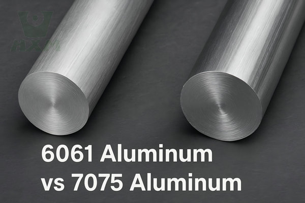
| 6061 | Good general anodizing response | Widely used, predictable |
| 6063 | Excellent decorative response | Good for appearance-critical parts |
| 7075 | Functional anodizing possible | Color variation, process sensitivity |
| 2024 | More challenging due to copper content | Appearance and corrosion variability |
| Cast aluminum | Less uniform | Porosity and inconsistent finish |
For buyers, this means the drawing should not only specify anodizing type and thickness. It should also align the alloy choice with the expected finish class. A part designed for premium cosmetic clear anodize will behave differently in 6063 than in 7075.
Sealing, Porosity, and Thickness Stability
After anodizing, sealing affects corrosion performance, stain resistance, and long-term durability. Common sealing methods include hot deionized water sealing and nickel acetate sealing. Proper sealing closes the pores of the anodic layer, improving corrosion resistance. However, sealing can also slightly affect dimensions, surface feel, and appearance.
Sealing considerations
- clear anodized parts often require strong sealing for appearance and corrosion protection
- hardcoat parts may be left unsealed in specific wear applications, depending on function
- PTFE impregnation may be specified for friction reduction
- sealing quality can influence dielectric and contamination behavior
In precision parts, sealing is one more variable in the finished-condition tolerance plan.
Common Failure Modes Caused by Poor Thickness Tolerance Planning
1. Threads seize during assembly
The part passes pre-finish inspection but the post-anodize thread no longer matches the mating fastener.
2. Press-fit or slip-fit turns into interference
A housing bore receives hard anodize and the bearing no longer installs within force limits.
3. Grounding path is lost
Anodized coating covers an electrical contact area that should have been masked.
4. Cosmetic rejection across a mixed-alloy batch
Different alloys produce visible variation even with the same thickness target.
5. Dielectric target missed
Film thickness or sealing quality is insufficient for voltage isolation requirements.
6. Wear layer cracks at edge-loaded surfaces
Heavy hardcoat on sharp geometry without edge conditioning leads to localized failure.
Design Rules for Engineers Specifying Anodized CNC Parts
The most successful anodized components are designed for anodizing, not merely anodized after design.
Recommended design and sourcing rules
Specify final condition clearly
State whether dimensions apply:
- before anodizing
- after anodizing
- or only on selected critical features after anodizing
Mark critical surfaces
Identify:
- masked zones
- electrical contact zones
- sealing lands
- bearing fits
- threaded features
- cosmetic A-surfaces
Avoid unnecessary anodizing on precision fits
Where function depends on direct metal tolerance, consider masking or alternative surface treatment.
Add machining compensation
For controlled bores, shafts, and slots, include coating growth allowance in the CNC program.
Use realistic coating thickness
Do not request heavy hardcoat where Type II would meet the actual functional need.
Approve first article after finishing
Measure the finished part, not just the machined blank.
Coordinate alloy, roughness, and finish
An Ra value, bead blast condition, or toolpath texture can influence the visual and functional result of the anodized layer.
Application Case 1: Aerospace Sensor Mount with Tight Bore Tolerance
Project background
A customer in the aerospace supply chain required CNC machined 6061-T6 aluminum sensor mounts with corrosion protection, dielectric separation, and controlled fit on a locating bore. The drawing referenced Type II anodizing with a clear finish and tight dimensional tolerance on the bore and mounting face.
Problem
The first prototype lot was machined to final bore size before anodizing. After anodizing at approximately 15 µm thickness, the locating bore shrank enough to create assembly interference. At the same time, one grounding contact area had not been masked, eliminating required electrical continuity.
Technical analysis
- process: Type II Class 1 clear anodizing
- thickness: ~15 µm
- estimated inward growth effect on bore: ~7.5 µm per side
- total bore reduction: ~15 µm
- impact: mismatch against mating aerospace sensor body
- secondary issue: full-surface anodize interrupted electrical path
Corrective action
- pre-anodize bore oversize introduced into CNC program
- selective masking added to grounding pad
- measurement plan changed from pre-finish inspection to post-finish critical inspection
- surface preparation standardized to reduce lot-to-lot visual variation
Result
The revised process restored assembly fit, maintained corrosion protection, and met electrical function at the contact zone. More importantly, the customer updated the drawing to define finished-condition requirements explicitly.
Procurement lesson
In aerospace machining, anodizing thickness cannot be separated from fit and conductivity requirements. The right answer is rarely “anodize the whole part and check later.”
Application Case 2: Medical Device Housing Requiring Clean Appearance and Controlled Threads
Project background
A medical equipment manufacturer sourced compact aluminum housings for a handheld diagnostic device. The housing required a clean satin appearance, repeated cleaning resistance, and precise threaded closure engagement.
Problem
The original supplier used standard anodizing without compensating the thread geometry. The threads became too tight after finishing, causing inconsistent torque during assembly. Some parts also showed slight color and gloss variation that was unacceptable for a premium medical device enclosure.
Technical analysis
- alloy: 6061
- finish: clear Type II anodizing, sealed
- thickness target: 10-15 µm
- issue 1: female thread pitch diameter reduction after anodizing
- issue 2: cosmetic inconsistency due to variable pre-treatment and surface roughness
- issue 3: closure torque variation affecting assembly repeatability
Corrective action
- thread oversize strategy validated by trial run
- masking used on a critical sealing face
- bead blasting parameters standardized before anodizing
- thickness control tightened to a narrower process window
- lot approval included visual master samples and torque verification
Result
The manufacturer achieved smoother assembly, lower rejection rates, and better visual consistency across production batches. The finished housing met both engineering and brand requirements.
Procurement lesson
For medical device housings, a beautiful anodized finish is not enough. Thread function, cleanability, and consistency across lots matter just as much as nominal thickness.
If your product combines appearance requirements with precise assembly features, JLYPT can review those risk areas before tooling release: Custom Aluminum Anodizing Services
Application Case 3: Automotive Valve Block with Hard Anodized Wear Surfaces
Project background
An automotive customer required machined aluminum valve blocks used in a fluid control system. The part included precision bores, sliding interfaces, and exposure to repeated mechanical wear. Type III hard anodizing was requested to improve wear resistance.
Problem
The customer’s original print specified hard anodizing up to 50 µm on all internal surfaces while also holding very tight bore tolerance. This combination was not realistic without compensation or selective masking. Initial samples showed excessive bore reduction and inconsistent spool movement.
Technical analysis
- alloy: 6082 / 6061 equivalent production route
- finish: Type III hard anodizing
- target thickness: 40-50 µm
- estimated inward dimensional loss in bores: 40-50 µm total
- functional impact: spool clearance reduced below design target
- added concern: local thickness variation in intersecting passages
Corrective action
- critical sliding bores redefined as post-finish functional dimensions
- machining compensation updated
- some non-critical areas retained full hardcoat thickness
- process development run used to correlate anodize growth with actual bore shift
- assembly tested with representative fluid cycle conditions
Result
The revised design preserved wear resistance where needed while restoring spool movement and reducing hydraulic performance variation.
Procurement lesson
In automotive fluid and motion components, hard anodizing improves durability, but only if coating growth is built into the tolerance strategy. Uniform thickness across all surfaces is not always the best functional solution.
Choosing the Right Thickness for Your Application
There is no universal “best” anodizing thickness. The correct thickness is the thinnest coating that reliably achieves the required function with acceptable dimensional impact, appearance, and cost.
Quick selection guide
| Requirement | Likely Best Choice | Why |
|---|---|---|
| High cosmetic value, moderate protection | Type II, 8-15 µm | Good appearance, manageable growth |
| Dyed decorative parts | Type II, 10-20 µm | Better color uptake |
| Tight tolerance with limited growth allowance | Thin Type II, 5-10 µm | Lower dimensional shift |
| Heavy wear resistance | Type III, 25-50 µm | Strong wear layer |
| Electrical insulation | Type III, 35-60 µm | Better dielectric capability |
| Precision threaded part | Masked Type II or selective Type III | Limits thread interference |
| Sliding hydraulic element | Controlled hardcoat with validation | Needs wear and clearance balance |
RFQ Checklist for Buyers Ordering Anodized CNC Parts
A strong RFQ prevents surprises. If you are sourcing anodized machined parts, include the following information whenever possible.
Buyer checklist
- aluminum alloy grade
- CNC machining tolerance on critical features
- anodizing type: Type II or Type III
- class: clear/natural or dyed
- coating thickness target and acceptable tolerance
- standard reference, such as MIL-A-8625 if applicable
- sealed or unsealed requirement
- masking zones
- critical post-finish dimensions
- cosmetic approval standard
- corrosion or salt spray requirement if relevant
- dielectric or wear requirement if relevant
- first article inspection expectations
- thread fit class and whether threads should be masked
This level of detail helps the supplier plan machining allowance, fixture design, coating control, and inspection method.
How JLYPT Helps Reduce Anodizing Tolerance Risk
JLYPT supports customers who need anodized aluminum components with both machining accuracy and production practicality. The key advantage is not simply access to anodizing. It is the ability to review the part as a full manufacturing system.
That includes:
- identifying coating-sensitive dimensions before release
- recommending Type II vs Type III based on function
- advising masking strategy for threads, bores, and electrical contact areas
- aligning machining offsets with target anodizing thickness
- managing visual expectations for different alloys and finishes
- reducing rework and fit-related rejection in pilot and mass production
For engineering teams, that shortens the trial-and-error loop. For purchasing teams, it reduces hidden cost from scrap, delayed assembly, and supplier change orders.
If you have a drawing with tight bores, threaded holes, cosmetic surfaces, or hardcoat wear requirements, send it for review before production. JLYPT’s anodizing and machining support page is here: Custom Aluminum Anodizing Services
Frequently Asked Questions
Does anodizing always increase part size?
Not exactly. The oxide layer grows partly outward and partly inward. External dimensions usually increase, while internal openings usually decrease.
How much dimensional change should I expect?
That depends on coating thickness and process conditions. A practical planning estimate is that about half of the total coating thickness contributes to outward dimensional growth on each coated surface.
Is Type III always better than Type II?
No. Type III offers better wear resistance and stronger dielectric behavior, but it causes more dimensional change, has a darker appearance, and may be unnecessary for many housings or cosmetic parts.
Can threads be anodized successfully?
Yes, but thread fit must be engineered carefully. Fine threads and tight thread classes often require masking, oversize tapping strategy, or post-treatment correction.
Does thicker anodizing always mean better corrosion resistance?
Not automatically. Corrosion resistance depends on thickness, pore structure, alloy, pretreatment, sealing quality, and service environment.
Should dimensions on the drawing apply before or after anodizing?
For critical features, dimensions should usually be defined in the finished condition, or the drawing should explicitly identify which features are controlled after anodizing.
Final Thoughts: Thickness Tolerance Is a Design Decision, Not a Finishing Detail
Anodizing thickness tolerance impacts far more than surface appearance. It changes fits, alters functional geometry, influences wear behavior, affects dielectric breakdown performance, and can determine whether a precision CNC part assembles correctly or becomes scrap.
Type II and Type III anodizing each have valid roles in industrial manufacturing, but neither should be selected by habit alone. The right process depends on the part’s dimensional tolerance, wear profile, electrical requirements, alloy, and assembly method.
For engineers, the best practice is simple: design and tolerance the part in its finished condition.
For buyers, the best practice is just as clear: choose a supplier that understands both machining and anodizing as one connected process.
That is where many projects either lose margin or gain reliability.
When you need aluminum CNC parts with controlled anodizing thickness, cosmetic consistency, and manufacturable tolerances, JLYPT can help evaluate the print and recommend a workable process path before production begins. Start here: Custom Aluminum Anodizing Services