7075 Anodizing Issues and Solutions for CNC Parts
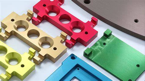
7075 aluminum is one of the most widely specified high-strength alloys in aerospace, defense, robotics, motorsports, and structural performance applications. It delivers an excellent strength-to-weight ratio and machines well, which is why many CNC buyers choose it for critical brackets, housings, fixtures, frames, and precision assemblies. But when surface finishing enters the process, 7075 behaves differently from more anodizing-friendly alloys such as 6061.
That difference matters.
Many purchasing teams and engineers discover the problem only after parts come back from finishing with color variation, pitting, gray smut, edge burn, dimensional shift, poor corrosion performance, or rejected cosmetic appearance. In extreme cases, the anodic coating may fail continuity requirements, lose adhesion quality at sharp features, or show dielectric breakdown under aggressive hardcoat conditions. These issues can delay launches, trigger rework, and increase the total cost of ownership.
The good news is that most 7075 anodizing problems are predictable and preventable. They are usually linked to a specific combination of alloy chemistry, machining condition, part geometry, pretreatment sequence, anodizing chemistry, fixturing, current density, sealing method, and tolerance planning.
This guide explains the most common 7075 anodizing issues and solutions for CNC machined parts. It is written for B2B sourcing teams, product engineers, quality managers, and manufacturing buyers who need both technical clarity and supplier-level execution guidance.
If you are sourcing custom machined aluminum parts that require reliable anodized finishes, JLYPT provides integrated CNC machining and finishing support. You can review the company’s anodizing capabilities here: custom aluminum anodizing services.
Why 7075 Aluminum Is More Challenging to Anodize
7075 is a zinc-rich aluminum alloy, typically containing zinc as the primary alloying element along with magnesium and copper. A representative nominal composition often falls near:
- Zinc: 5.1–6.1%
- Magnesium: 2.1–2.9%
- Copper: 1.2–2.0%
- Chromium: 0.18–0.28%
- Aluminum: balance
These alloy additions are the reason 7075 performs so well mechanically. In T6 condition, it can achieve tensile strengths in the range of roughly 510–570 MPa depending on product form and specification. However, the same alloy chemistry also affects anodizing behavior.
Why the alloy chemistry matters in anodizing
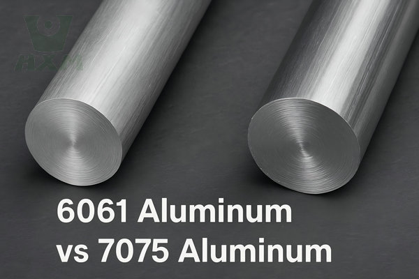
Compared with 6061, 7075 tends to show:
- More visible etch variation
- Greater risk of non-uniform appearance
- Higher sensitivity to pretreatment errors
- Increased tendency toward smut formation due to copper-bearing intermetallics
- Greater difficulty in achieving decorative cosmetic consistency
- Hardcoat process sensitivity at edges and high-current-density areas
This does not mean 7075 should not be anodized. It means it must be anodized with process discipline.
In many applications, especially structural and wear-focused parts, Type II or Type III anodizing on 7075 is a strong and reliable finishing route when the processor controls:
- Surface preparation
- Rack contact strategy
- Electrical loading
- Bath temperature
- Sulfuric acid concentration
- Time-to-thickness control
- Sealing chemistry
- Final inspection against print and specification
Understanding Type II and Type III Anodizing on 7075
Before discussing defects, it is important to define the two anodizing routes most often used for CNC 7075 parts.
Type II anodizing
Type II sulfuric acid anodizing is typically used when the priorities are:
- Corrosion resistance
- Decorative appearance
- Moderate wear resistance
- Dyeing capability
- Lower thickness buildup than hardcoat
This process generally produces a thinner oxide layer and is often selected when a part needs:
- Black, clear, blue, red, or custom dyed colors
- Better cosmetic finish than a heavy hardcoat
- Moderate dimensional growth
- General industrial corrosion protection
Type III anodizing
Type III, often called hard anodizing or hardcoat anodizing, is used when the priorities are:
- High wear resistance
- Improved abrasion performance
- Higher coating thickness
- Better dielectric properties
- Functional rather than decorative finish
- Greater surface hardness
For 7075 machined parts, Type III is common in:
- Aerospace wear surfaces
- Sliding components
- Mechanical housings
- Tactical equipment
- Automotive performance parts
- Fixtures exposed to repeated contact or friction
Reference standard
The most recognized U.S. military specification is MIL-A-8625. It is now often referenced in practice alongside its successor framework, but the market still commonly calls out “MIL-A-8625 Type II” or “MIL-A-8625 Type III.” Buyers, engineers, and finishers should clearly define:
- Type
- Class
- Thickness
- Color
- Sealing requirement
- Areas to mask
- Critical dimensions before and after anodize
Key 7075 Anodizing Standards and Typical Thickness Ranges
The table below summarizes practical thickness ranges often used in manufacturing, aligned with common industry practice and MIL-A-8625 style callouts.
Table 1: Typical anodizing thickness ranges for 7075 aluminum
| Anodizing Type | Common Specification Reference | Typical Thickness Range | Typical Inch Range | Primary Purpose | Cosmetic Quality |
|---|---|---|---|---|---|
| Type II, Class 1 | MIL-A-8625 Type II Class 1 | 5–18 µm | 0.0002″–0.0007″ | Clear corrosion protection | Moderate to good |
| Type II, Class 2 | MIL-A-8625 Type II Class 2 | 8–25 µm | 0.0003″–0.0010″ | Dyed decorative + corrosion protection | Good if process-controlled |
| Type III, Class 1 | MIL-A-8625 Type III Class 1 | 25–75 µm | 0.0010″–0.0030″ | Hardcoat, wear resistance | Functional |
| Type III, Class 2 | MIL-A-8625 Type III Class 2 | 25–75 µm | 0.0010″–0.0030″ | Hardcoat + dyed dark finish | Functional, color variation possible |
Important thickness note
Anodic coatings grow both outward and inward relative to the original aluminum surface. A common planning assumption is:
- About 50% buildup outward
- About 50% penetration inward
Actual distribution depends on alloy, bath chemistry, and processing conditions. For tolerance planning, engineers should not assume zero dimensional effect.
Dimensional Tolerance Impact on 7075 Anodized Parts
Dimensional control is one of the most overlooked issues in 7075 anodizing. Precision CNC parts often fail assembly not because the coating is defective, but because the designer did not account for anodic buildup.
Table 2: Approximate dimensional effect from anodizing thickness
| Coating Thickness | Approx. Outward Growth Per Surface | Hole Diameter Reduction | Shaft/OD Increase |
|---|---|---|---|
| 10 µm | 5 µm | ~10 µm | ~10 µm |
| 15 µm | 7.5 µm | ~15 µm | ~15 µm |
| 25 µm | 12.5 µm | ~25 µm | ~25 µm |
| 50 µm | 25 µm | ~50 µm | ~50 µm |
Example
If a 7075 precision pin seat hole is machined to 10.000 mm and then receives a 25 µm anodic coating, the final hole may shrink by approximately 0.025 mm, leaving an effective diameter around 9.975 mm, depending on actual coating distribution.
Why this creates problems
7075 is often used in:
- Interference-fit assemblies
- Bearing seats
- Threaded components
- Precision bores
- Sliding interfaces
- Tight-stack aerospace brackets
If dimensional tolerance is already narrow, anodizing can push the feature out of spec.
Practical solutions
- Pre-compensate dimensions during CNC machining
- Mask critical fit surfaces
- Specify maximum anodize thickness on mating features
- Use selective post-machining only when cost-justified
- Define whether dimensions apply before anodize or after anodize
- Call out threads as masked if fit class is critical
If you need engineering support on tolerance compensation for anodized parts, JLYPT can review your drawings before production. See: custom aluminum anodizing services.
Common 7075 Anodizing Issues and Their Root Causes
Below are the most common failure modes seen on 7075 CNC machined parts.\
1. Color Inconsistency
Color inconsistency is one of the biggest complaints when anodizing 7075, especially in black or other dyed Type II finishes.
Typical appearance
- Part-to-part shade variation
- Batch-to-batch mismatch
- Uneven darkening near edges
- Gray or brown undertones
- Patchy appearance on machined surfaces
Why it happens
7075 does not anodize as cosmetically uniformly as 6061 because of:
- Higher copper and zinc content
- Variable grain orientation
- Surface roughness differences from machining
- Non-uniform etching
- Inconsistent de-smut treatment
- Variation in coating thickness
- Dye absorption differences
Common triggers
- Mixed alloy loads in one anodizing run
- Surface finish inconsistency between toolpaths
- Residual coolant contamination
- Uneven alkaline etch attack
- Under- or over-desmutting
- Inconsistent sealing
Solutions
- Run 7075 separately from 6061 when cosmetic consistency matters
- Standardize Ra finish before anodizing
- Use consistent tooling and finishing paths
- Apply controlled etch rather than aggressive decorative etching
- Use proper nitric-based de-smut where required
- Keep dye concentration, pH, and immersion time tightly controlled
- Match loads by alloy, temper, geometry, and finish history
- Approve a realistic cosmetic standard before production
Buyer guidance
If your part is customer-facing and requires premium cosmetic black anodize, ask your supplier whether 7075 is the best alloy choice. In some products, moving to 6061 for cosmetic parts and reserving 7075 for structural hidden parts reduces rejection rates.
2. Burning and Edge Overheating
Burning is especially important in Type III hard anodizing. It appears as:
- Dark, rough, powdery areas
- Edge scorching
- Coating roughness
- Localized breakdown near corners or rack contacts
Technical cause
Anodizing is an electrochemical oxidation process. Sharp edges and thin sections concentrate current density. If local current exceeds stable process limits, the coating may overheat, causing:
- Oxide instability
- Surface roughening
- Localized dissolution
- Dielectric breakdown
- Dark burnt appearance
Factors that increase burn risk
- Sharp external corners
- Thin walls
- Poor fixturing
- Inadequate agitation
- Excessive current ramp rate
- High bath temperature
- High resistance at rack contact
- Heavy coating targets on complex geometry
Solutions
- Add edge radii in design where possible
- Use gradual current ramping instead of abrupt load application
- Improve fixturing for stable electrical contact
- Maintain low temperature for Type III processing
- Increase bath agitation and cooling capacity
- Reduce target thickness at burn-prone locations
- Hardcoat critical geometries in optimized smaller loads
Design recommendation
A sharp machined edge may be acceptable on a print, but it is not always compatible with stable hard anodizing. Even a small radius can improve coating quality and reduce scrap.
3. Pitting and Surface Voids
Pitting can appear before anodizing, during pretreatment, or after coating when defects become more visible.
Typical sources
- Embedded contamination from machining
- Corrosion initiated during storage
- Chloride exposure before finishing
- Poor rinsing between process tanks
- Surface attack from improper etching
- Metallurgical inclusions or intermetallic exposure
On 7075 specifically
Copper-bearing intermetallics and segregated phases can make the alloy less forgiving. Improper cleaning and de-smut can leave residues that later appear as pits or crater-like defects after anodizing.
Solutions
- Keep parts clean and dry after machining
- Minimize delay between machining and finishing
- Avoid chloride contamination
- Use proper alkaline clean followed by controlled etch and de-smut
- Audit rinse water quality
- Review upstream machining damage under magnification
- Use incoming surface inspections for critical aerospace or medical parts
4. Smut and Residue After Etching
Smut is common on alloys with higher copper and alloying content, including 7075.
What it looks like
- Gray, black, or brown residue
- Patchy surface after etch
- Streaking before anodizing
- Uneven final finish
Root cause
During alkaline etching, aluminum dissolves while less soluble alloy constituents can remain as residue. On 7075, copper-rich remnants often require strong de-smut control.
Solutions
- Avoid excessive etch time
- Use de-smut chemistry appropriate for 7xxx alloys
- Maintain chemistry concentration and dwell time
- Replace exhausted de-smut baths on schedule
- Confirm complete rinsing after de-smut
- Validate process with test panels or witness samples
Without full smut removal, the anodic layer can become non-uniform and cosmetic defects increase sharply.
5. Poor Corrosion Resistance After Anodizing
Some buyers assume that any anodized 7075 part is automatically corrosion resistant. That assumption is risky.
Why corrosion failures occur
- Coating too thin for service environment
- Pores not properly sealed
- Damaged coating during assembly
- Excessive porosity from unstable process conditions
- Wrong anodizing type for field exposure
- Salt spray demands higher than process capability
- Bare contact points left exposed without planning
Sealing matters
Anodized coatings are porous before sealing. Seal quality strongly influences:
- Corrosion resistance
- Dye retention
- Surface cleanliness
- Electrical behavior
- Long-term field durability
Common sealing options include:
- Hot DI water sealing
- Nickel acetate sealing
- Mid-temperature sealing
- PTFE-enhanced or specialty functional sealing in some systems
Practical solution path
- Match coating thickness to environment
- Specify sealing method, not just anodizing type
- Avoid cosmetic-only assumptions for outdoor or marine exposure
- Protect rack marks and contact points if they are in critical service areas
- Validate with salt spray or application-specific testing when required
6. Inadequate Wear Resistance
Wear resistance is often the reason buyers choose Type III on 7075. But not every “hard anodized” part delivers the same tribological performance.
Reasons for underperformance
- Coating too thin
- Low hardness due to process drift
- Improper sealing for wear application
- Surface roughness too high before anodizing
- Counterface incompatibility in sliding assembly
- Edge chipping on overloaded geometry
Wear-related guidance
Type III coatings generally provide much better wear resistance than Type II. However:
- Excessive thickness on delicate features may crack or spall
- Rough pre-machined surfaces can increase friction
- Some sealing methods can slightly reduce maximum abrasion performance
- Coating alone may not solve lubrication problems
Solution strategy
- Define the actual wear mode: abrasion, sliding, fretting, or impact
- Choose thickness based on service condition
- Review counter-material and lubrication
- Set a realistic surface roughness before finishing
- Test in actual operating conditions rather than relying only on nominal coating class
7. Cracking, Chipping, or Coating Damage at Edges
This issue often appears on:
- Thin tabs
- Knife edges
- Internal corners
- Deep-pocket transitions
- Hard-anodized threads
Why it happens
Thick anodic coatings are ceramic-like and relatively brittle compared with the base aluminum. On unsupported or highly stressed features, the coating can fracture mechanically.
Solutions
- Reduce coating thickness on delicate geometry
- Add chamfers or radii
- Mask threads if assembly fit is critical
- Avoid heavy hardcoat on flexing features
- Reevaluate whether Type II plus design reinforcement may be a better choice
8. Thread Fit Problems
Anodizing changes thread dimensions. Internal threads close up; external threads grow. On 7075 components used in aerospace and automotive fixtures, this is a common rejection source.
Table 3: Thread and fit considerations after anodizing
| Feature Type | Typical Anodizing Effect | Risk Level | Common Solution |
|---|---|---|---|
| Internal threads | Pitch diameter decreases | High | Mask threads or oversize machine |
| External threads | Pitch diameter increases | High | Mask threads or rework if allowed |
| Precision bores | Diameter decreases | High | Pre-compensate or mask |
| Bearing seats | Fit interference changes | Very high | Mask or post-machine |
| Cosmetic exterior surfaces | OD increases | Low to medium | Allow in print tolerance |
Best practice
Do not leave thread treatment ambiguous on the drawing. State clearly:
- Mask threads
- Chase threads after finish
- Oversize before finish
- No anodize permitted on mating threads
For high-value parts, this decision should happen during DFM review, not after first article failure.
9. Poor Adhesion of Subsequent Marking or Bonding
Some anodized 7075 parts require:
- Laser marking
- Adhesive bonding
- Painting over anodize
- Conductive inserts
- Potting compounds
Problems arise if the anodized surface is:
- Sealed too aggressively for bonding
- Contaminated after finishing
- Too rough or too smooth for the downstream process
- Not specified for dual-function performance
Solution
Define downstream requirements early. “Anodized” is not enough. The finisher should know whether the part also requires:
- Bondable surface
- Laser-readable contrast
- Electrical insulation
- Controlled friction
- Sterilization resistance
- Medical cleaning compatibility
Type II vs Type III on 7075: Which One Fits the Application?
Table 4: Type II vs Type III anodizing for 7075 CNC parts
| Criteria | Type II Anodizing | Type III Hard Anodizing |
|---|---|---|
| Typical thickness | 5–25 µm | 25–75 µm |
| Appearance | Better for decorative color | More functional, darker natural tone |
| Dyeing | Excellent for color options | Limited, often dark shades |
| Wear resistance | Moderate | High |
| Corrosion resistance | Good when sealed | Good to very good when processed correctly |
| Dimensional impact | Lower | Higher |
| Risk of burn on sharp edges | Lower | Higher |
| Cost | Lower to moderate | Higher |
| Best use | Cosmetic + general protection | Heavy-duty wear and functional surfaces |
Quick selection guide
Choose Type II when:
- Appearance matters more than extreme wear
- Part has tighter dimensional tolerance
- Dyed color consistency is needed
- The service environment is moderate
Choose Type III when:
- Wear resistance is critical
- Functional hardness matters
- The part sees friction or repeated handling
- A thicker functional coating is acceptable
7075 Anodizing Pretreatment: Where Quality Is Won or Lost
For 7075, pretreatment often determines whether the final finish looks premium or problematic.
Recommended pretreatment sequence
A robust process may include:
- Solvent or alkaline cleaning
- Rinse
- Controlled alkaline etch or non-etch clean depending on cosmetic target
- Rinse
- De-smut / deoxidize
- Rinse
- Anodize
- Rinse
- Dye if required
- Seal
- Final rinse and dry
- Inspection
Process control priorities
- Cleaner concentration
- Etch rate control
- De-smut chemistry health
- Rack contact integrity
- Water quality
- Time between stages
- Temperature stability
- Bath contamination management
Machining-to-finishing link
Surface condition from CNC machining directly affects anodizing outcome. Tool marks, recast-like smearing, trapped coolant, and inconsistent deburring all show up more strongly after anodizing.
For that reason, the best suppliers integrate CNC process planning with finishing requirements rather than treating anodizing as a separate final step.
Recommended Surface Roughness Before Anodizing
Surface roughness is not a single standard value across all industries, but roughness planning is essential.
General guidance
- For cosmetic Type II parts: lower and more uniform Ra is preferred
- For hardcoat functional parts: slightly rougher substrate may be acceptable depending on wear application
- Overly rough machined surfaces can magnify visual variation after dyeing
- Bead blasting can improve visual uniformity, but it changes dimensional and cosmetic behavior
Table 5: General roughness guidance by finish objective
| Finish Objective | Suggested Pre-Anodize Surface Condition | Notes |
|---|---|---|
| Premium cosmetic dyed Type II | Fine uniform machined or light bead blast | Best for visual consistency |
| Clear Type II industrial | Standard machined finish | Moderate cosmetic expectation |
| Type III hardcoat wear surface | Controlled machined finish or specified blast | Verify final roughness against function |
| Tight tolerance bores | Machined and masked | Avoid buildup if fit is critical |
Real Application Case 1: Aerospace Bracket with Hardcoat Burn at Edges
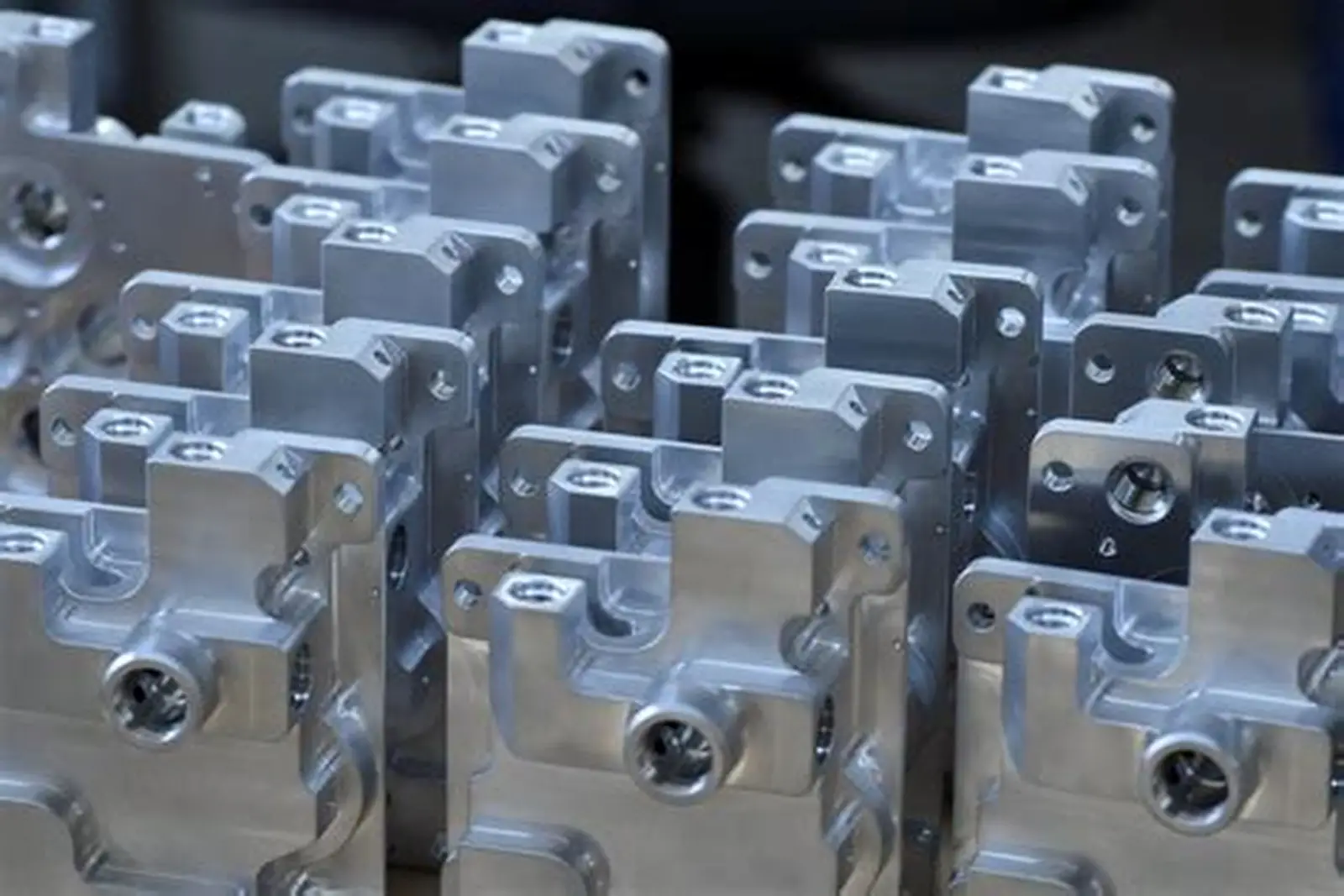
Background
A customer manufacturing lightweight aerospace electronic support brackets selected 7075-T6 for strength reduction compared with steel. The parts were CNC machined with several thin ribs, sharp external corners, and a MIL-A-8625 Type III hardcoat requirement at 50 µm nominal thickness.
Problem
The first finishing batch showed:
- Dark burn marks at rib edges
- Rough coating near corner transitions
- Two parts with rejected appearance and one with local thickness inconsistency
Root cause analysis
The issue was not random. It came from a combination of:
- Sharp edge geometry
- Thin rib sections
- Aggressive target thickness
- High local current density during hardcoat growth
This is a classic 7075 hard anodizing problem where edge current concentration increases the risk of overheating and dielectric breakdown.
Corrective action
The process team applied four changes:
- Added a controlled radius to the most critical edges in the next CNC revision
- Reduced abrupt current ramp at process start
- Adjusted fixturing to improve load balance
- Tuned thickness target by function rather than applying the same maximum to every feature
Result
The revised process reduced visible burn defects and improved thickness uniformity. Scrap dropped significantly, and the customer accepted a defined cosmetic standard focused on functional aerospace requirements rather than decorative appearance.
Procurement takeaway
For aerospace 7075 hardcoat parts, coating performance and geometry compatibility should be reviewed together. Specifying the maximum possible thickness everywhere is not always the best engineering choice.
Real Application Case 2: Medical Device Housing with Cosmetic Black Shade Variation
Background
A medical equipment OEM used CNC machined 7075 housings for a lightweight handheld device. The requirement was black Type II anodizing with a premium external cosmetic finish.
Problem
The customer saw:
- Shade variation between production lots
- Slightly different black tone between front and rear housing components
- Increased rejection rate during final assembly visual inspection
Root cause analysis
The issue was traced to:
- Different machining surface conditions on mating components
- Slight pretreatment variation between lots
- Natural cosmetic limitations of 7075 compared with 6061 for dyed anodized appearance
Corrective action
The solution package included:
- Standardizing the toolpath and final surface finish on all visible faces
- Applying controlled bead blasting before anodize to improve visual uniformity
- Running matched components in the same anodizing lot
- Tightening dye bath control and approval criteria with a retained color master sample
Result
Visual consistency improved enough for production release. The customer retained 7075 for structural performance but accepted a cosmetic control window based on sample approval rather than unrealistic “perfect black” wording.
Procurement takeaway
For medical products with visible anodized surfaces, supplier process capability and approval method matter as much as the alloy selection. If cosmetic black is mission-critical, evaluate 6061 versus 7075 during design.
Real Application Case 3: Automotive Performance Component with Thread Fit Failure
Background
An automotive aftermarket manufacturer sourced 7075 CNC suspension adjustment collars requiring hard anodizing for wear resistance and environmental durability.
Problem
After Type III anodizing, the internal thread engagement became too tight, and several mating parts seized during assembly. The machined threads had been cut to nominal print size before finishing.
Root cause analysis
The issue came from anodic buildup reducing the effective pitch diameter of the internal threads. The supplier had followed the coating callout but the drawing did not clarify whether threads should be masked or compensated before finish.
Corrective action
The revised manufacturing plan included:
- Explicit thread masking on critical internal threads
- Hard anodizing only on non-thread wear surfaces
- Drawing note updates defining anodize exclusion zones
- First article verification with thread gauges after finishing
Result
Assembly yield improved, rework costs dropped, and the product achieved the intended wear performance without thread seizure.
Procurement takeaway
When anodizing 7075 threaded parts, thread strategy must be defined on the print. If not, dimensional drift will become a quality escape.
How to Prevent 7075 Anodizing Failures in Production
Most defects can be prevented with a disciplined pre-production workflow.
1. Match alloy selection to finish expectations
Use 7075 when strength is needed. If premium decorative anodized appearance is the priority, compare alternatives such as 6061.
2. Define coating type precisely
Do not specify only “anodize.” State:
- Type II or Type III
- Class 1 or Class 2
- Clear or dyed color
- Target thickness
- Masking zones
- Sealing requirement
- Inspection method
3. Review geometry for anodizing compatibility
Flag:
- Sharp corners
- Thin walls
- Deep recesses
- Tight bores
- Fine threads
- Unreachable rack contact areas
4. Account for dimensional tolerance
Identify dimensions that apply:
- Before anodize
- After anodize
- On masked surfaces only
5. Standardize machining finish
Uniform tool marks lead to more uniform anodize.
6. Control pretreatment tightly
Many “anodizing” defects actually begin in cleaning, etching, or de-smut.
7. Use first article approval with finish criteria
For critical programs, verify:
- Coating thickness
- Color standard
- Fit check
- Surface roughness
- Salt spray if needed
- Functional wear where applicable
Inspection and Quality Control for 7075 Anodized Parts
A serious supplier should have documented inspection criteria for anodized CNC parts.
Common QC checkpoints
- Coating thickness measurement
- Visual appearance under controlled lighting
- Color comparison to approved standard
- Dimensional inspection after finishing
- Thread gauge verification
- Adhesion or process validation checks
- Seal quality tests where required
- Corrosion testing for qualification programs
Table 6: Typical inspection focus by application
| Industry | Main Anodizing Priority | Typical QC Focus |
|---|---|---|
| Aerospace | Functional durability, spec compliance | Thickness, visual defects, masking, traceability |
| Medical | Clean cosmetic finish, repeatability | Color, surface cleanliness, dimensional fit |
| Automotive performance | Wear resistance, fit, cost control | Thread fit, hardness-related performance, batch consistency |
| Electronics | Cosmetic + insulation | Color, dielectric behavior, appearance |
| Industrial automation | Corrosion + wear | Thickness, surface damage, practical durability |
Practical Tolerance Planning Table for Buyers and Engineers
Table 7: Tolerance planning suggestions for 7075 anodized features
| Feature | If Type II is Used | If Type III is Used | Recommended Action |
|---|---|---|---|
| General exterior face | Usually manageable | Buildup more significant | Allow coating in tolerance stack |
| Precision hole | Diameter reduction likely | Diameter reduction significant | Oversize or mask |
| Bearing journal | OD increase likely | OD increase significant | Mask or post-process |
| Internal thread | Fit reduction | Major fit reduction | Mask or compensate |
| Sliding wear track | Moderate improvement | Strong improvement | Consider hardcoat |
| Cosmetic front face | Good with process control | More functional than decorative | Choose based on real priority |
Choosing the Right 7075 Anodizing Supplier
For B2B buyers, supplier capability is often the difference between repeatable production and recurring NCRs.
Ask these questions before placing the order
- Do you process 7075 regularly, or mostly 6061?
- Can you support both Type II and Type III anodizing?
- Do you work to MIL-A-8625 style requirements?
- How do you control color variation on 7075?
- How do you manage thread masking and tolerance compensation?
- Can you inspect coating thickness and post-finish dimensions?
- Can you support mixed CNC + finishing engineering review before production?
- Do you provide sample approval or first article validation?
What strong suppliers do differently
- Review drawings before quoting
- Flag unrealistic cosmetic requirements
- Recommend masking where needed
- Align machining strategy with finish outcome
- Separate decorative and functional priorities
- Provide traceable process control
JLYPT supports CNC machined aluminum parts with finishing-oriented manufacturability review, including anodizing considerations for precision components. If you are sourcing 7075 parts and want to reduce cosmetic rejects, tolerance issues, or hardcoat failures, you can contact the team here: custom aluminum anodizing services.
Frequently Asked Questions About 7075 Anodizing
Can 7075 aluminum be anodized successfully?
Yes. 7075 can be anodized successfully with both Type II and Type III processes. However, it is more sensitive than 6061 to cosmetic variation, smut, and process inconsistency.
Why does 7075 black anodizing look different from 6061?
Because alloy chemistry affects oxide formation and dye absorption. The zinc and copper content in 7075 often leads to a less uniform decorative result than 6061.
Is Type III hard anodizing good for 7075?
Yes. 7075 is widely hard anodized for wear resistance and functional durability. The main risks are edge burn, dimensional growth, and coating brittleness on delicate features.
Does anodizing change dimensions?
Yes. The coating adds measurable thickness. Holes get smaller, external diameters get larger, and thread fit changes unless masked or compensated.
Which is better for 7075, Type II or Type III?
Neither is universally better. Type II is usually better for color and appearance. Type III is better for wear resistance and heavy-duty functional use.
Why does 7075 form smut during pretreatment?
Its alloying elements, especially copper-bearing phases, can remain as residue after alkaline etching. Proper de-smut is essential before anodizing.
Best Practices Summary
If you want stable results when anodizing 7075 CNC machined parts, follow these principles:
- Use 7075 for strength, not purely for cosmetic anodize appearance
- Specify Type II or Type III clearly
- Define thickness, color, class, and sealing
- Plan for dimensional tolerance change
- Mask threads, bores, and critical fits where necessary
- Standardize machining surface finish
- Control etch and de-smut carefully
- Avoid sharp-edge hardcoat designs when possible
- Validate color and appearance with approved samples
- Choose a supplier that understands both CNC machining and anodizing
Final CTA: Reduce 7075 Anodizing Risk Before Production
7075 is an excellent alloy for high-strength CNC parts, but it does not forgive weak finishing control. Most anodizing failures on 7075 are not material defects. They are specification, design, pretreatment, fixturing, or process-control problems.
If your team is preparing a new RFQ or trying to fix recurring anodizing rejects on 7075 aluminum parts, getting engineering input before production is the fastest way to reduce cost and delays.
Need support on 7075 Type II or Type III anodizing for custom CNC parts?
Talk to JLYPT for machining + finishing guidance, drawing review, and production-ready anodizing support:
https://www.jlypt.com/custom-aluminum-anodizing-services/