Anodizing Color Matching for Production Parts: A Practical Guide for CNC Buyers and Engineers
When a production aluminum part looks slightly different from the approved sample, most customers notice it immediately. Engineers may focus on dimensional tolerance, coating thickness, corrosion resistance, dielectric performance, or wear resistance. Procurement teams often focus on cost, lead time, and supplier responsiveness. End users, however, notice color first.
That is why anodizing color matching for production parts is not a cosmetic detail. It is a production control issue, a quality assurance issue, and, in many industries, a brand issue.
For CNC machined aluminum parts, color matching in anodizing is more complex than many buyers expect. Two parts made from different aluminum grades can anodize differently even when processed in the same tank. Two lots from the same alloy can show visible shade variation if surface finish, racking, oxide thickness, dye concentration, sealing conditions, or bath chemistry are not tightly controlled. A part with aggressive machining marks may reflect light differently than a bead-blasted one, even if the anodized layer meets the same thickness specification. Large production runs make the challenge more difficult because process drift accumulates over time.
For B2B buyers sourcing production parts, the question is not simply “Can you anodize this part black, blue, or clear?” The real question is:
- Can the supplier repeat the approved color over multiple lots?
- Can they manage alloy-to-alloy variation?
- Can they control oxide thickness within specification?
- Can they preserve dimensional tolerance while achieving visual consistency?
- Can they document the process to standards such as MIL-A-8625 / MIL-PRF-8625?
- Can they support cosmetic requirements without compromising function?
At JLYPT, these questions are central to production planning for aluminum CNC parts with anodized finishes. If you are evaluating suppliers for appearance-critical and performance-critical components, you can review JLYPT’s capabilities here: custom aluminum anodizing services.
This guide explains how anodizing color matching works in real production, what variables change the result, what standards matter, how tolerances are affected, and how buyers can reduce risk before placing a full-volume order.
Why Color Matching Matters in Production Anodizing
In prototype work, a slight color variation may be acceptable. In production, it often is not.
Color variation can create problems in several ways:
- Brand inconsistency for consumer-facing or visible industrial products
- Assembly mismatch when parts from different lots appear different after assembly
- Inspection rejection when visual standards are not defined but buyers expect repeatability
- Rework and scrap costs when cosmetic deviation exceeds acceptance limits
- Delayed shipments caused by re-anodizing or lot segregation
- Supplier disputes when color expectation was subjective rather than documented
For production parts, color matching is especially important when:
- multiple parts are assembled side by side
- replacement parts must match installed units
- product lines use a brand-specific color
- medical or laboratory devices require a clean, premium appearance
- aerospace or automotive interiors require controlled visual quality
- customer-approved “golden samples” are used as the basis for lot acceptance
Anodizing can provide excellent corrosion resistance, good dielectric properties, improved wear resistance, and attractive appearance. But unlike paint, anodizing is a conversion coating grown from the substrate itself. This means the final appearance is highly dependent on the base metal and process conditions.
That is why a supplier that understands production anodizing color control is more valuable than one that only offers “anodizing” as a checkbox process.
What Anodizing Color Matching Really Means
Anodizing color matching does not mean every part is mathematically identical in color under all lighting conditions. In manufacturing reality, it means controlling the process tightly enough that parts remain within an agreed visual or instrumental acceptance range.
Color matching may be evaluated by:
- Visual comparison to a master sample
- Spectrophotometer measurements using Lab* values
- Lot-to-lot comparison under standard lighting conditions
- Customer-specific pass/fail criteria
- Sample retention and controlled reference panels
In production environments, acceptable color consistency usually depends on:
- the color itself
- the anodizing type
- alloy series
- pre-treatment finish
- part geometry
- batch size
- functional masking requirements
- end-use environment
- customer-defined acceptance standard
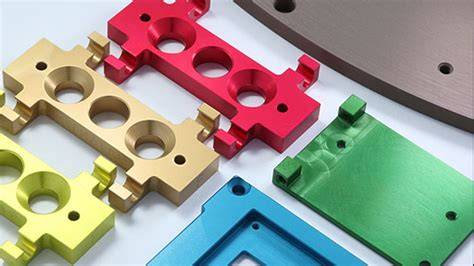
Black dyed Type II anodizing is often easier to hold consistently than lighter decorative colors. Clear anodizing can still vary visibly because “clear” anodized aluminum is not truly colorless; the alloy and oxide structure influence the final appearance. Bronze, red, blue, and other dyed finishes may shift when oxide pore structure or dye uptake changes. Hardcoat anodizing, especially Type III anodizing, usually results in darker gray to charcoal tones depending on alloy and process, and exact decorative color matching is much more limited.
Understanding the Main Anodizing Types Used for Production Parts
The first step in discussing color matching is understanding the anodizing classification.
Type II Anodizing
Type II sulfuric acid anodizing is the most common process for decorative and general industrial aluminum parts. It can be clear or dyed in many colors. It offers a balance of:
- corrosion resistance
- decorative appearance
- moderate wear resistance
- controllable oxide thickness
- compatibility with many machined aluminum parts
Typical applications include:
- electronic housings
- consumer device enclosures
- industrial covers
- brackets
- knobs
- medical equipment components
- automotive trim or visible hardware
Type III Anodizing
Type III hard anodizing produces a thicker, denser oxide layer with greater hardness and wear resistance. It is commonly used where abrasion resistance, dielectric strength, and durability are priorities.
Typical applications include:
- aerospace fittings
- hydraulic components
- wear surfaces
- automotive performance parts
- machine components
- military hardware
Color control in Type III is more restricted than in Type II. Natural hardcoat often appears gray, dark gray, olive-gray, or charcoal depending on alloy and process parameters. Black hardcoat is possible in some cases, but not all alloys and geometries will produce an exact deep cosmetic black.
Type I and Other Specialty Processes
Chromic acid anodizing and other specialty variants exist, but for most CNC production parts that require visible color matching, the main discussion is around Type II and Type III, often referenced under MIL-A-8625 legacy terminology or MIL-PRF-8625 in current procurement practice.
Industry Standards That Influence Color Matching Expectations
For professional buyers and engineers, standards matter because they define process classification and performance expectations. However, they do not guarantee perfect cosmetic uniformity unless the cosmetic requirement is separately defined.
Commonly Referenced Standards
| Standard | Scope | Relevance to Color Matching |
|---|---|---|
| MIL-A-8625 / MIL-PRF-8625 | Military specification for anodic coatings on aluminum | Defines Type I, II, III coatings, thickness/performance classes, but cosmetic matching must still be clarified |
| ISO 7599 | Anodizing of aluminum and its alloys | Useful for process and quality reference in international supply chains |
| ISO 10074 | Hard anodic oxidation coatings | Relevant for Type III style hard anodizing expectations |
| ASTM B244 | Measurement of anodic coating thickness | Important for thickness verification, which affects color |
| ASTM B487 | Cross-section measurement of coating thickness | Useful for more detailed coating evaluation |
| ASTM D2244 | Color measurement by instrumental methods | Helpful when quantifying color tolerance numerically |
| ASTM G155 / UV aging related methods | Environmental exposure validation | Useful for dyed anodized parts exposed to sunlight |
Important Clarification for Buyers
A part can fully comply with a thickness requirement under MIL-A-8625 and still show minor color variation from one lot to another. Thickness compliance is not the same as color compliance. If visual uniformity matters, your PO, drawing, approved sample, and quality plan should all state that requirement clearly.
The Science Behind Anodized Color Variation
To control color, it helps to understand why variation occurs.
Anodizing converts the aluminum surface into aluminum oxide through an electrolytic process. The oxide layer contains microscopic pores. In dyed Type II anodizing, these pores absorb dye before sealing. Several factors change how much dye is absorbed and how light is reflected from the surface.
Key Mechanisms That Change Color
- Alloy composition
- Surface roughness and reflectivity
- Oxide layer thickness
- Pore size and pore density
- Bath temperature
- Current density
- Acid concentration
- Dye chemistry and immersion time
- Sealing quality
- Racking contact points and current distribution
- Part geometry and edge effect
Even a small change in one parameter can shift the final appearance from the approved standard.
Main Factors Affecting Anodizing Color Matching for Production Parts
1. Aluminum Alloy Selection
Not all aluminum alloys anodize the same way. This is one of the biggest reasons for color mismatch in production.
General Alloy Behavior
- 6061: One of the most common anodizing-friendly alloys; generally produces good uniformity
- 6063: Often excellent for decorative anodizing; popular for architectural appearance
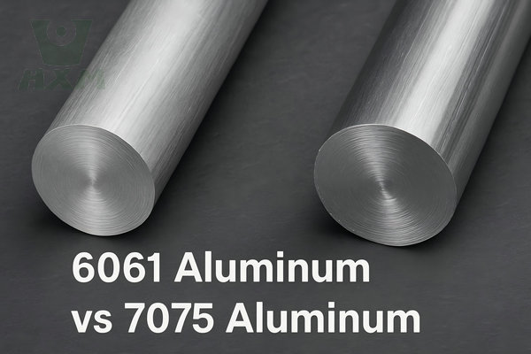
- 7075: Strong aerospace alloy, but copper and zinc content can shift color darker or less uniform
- 2024: High copper content often causes non-uniform appearance and is less suitable for decorative anodizing
- 5052: Can anodize well, but appearance differs from 6xxx alloys
- 6082: Similar family behavior to 6061 but may still differ visually depending on source and temper
Alloy Impact Table
| Aluminum Alloy | Typical Anodizing Appearance | Color Matching Risk | Common Production Use |
|---|---|---|---|
| 6061 | Uniform, good for dyed or clear anodize | Low to medium | General CNC parts, housings, brackets |
| 6063 | Very good decorative response | Low | Visible components, architectural parts |
| 5052 | Acceptable but appearance differs from 6xxx | Medium | Covers, sheet metal components |
| 7075 | Darker, less predictable for cosmetics | Medium to high | Aerospace, structural, performance parts |
| 2024 | Poor decorative consistency due to Cu content | High | Aerospace structural parts, not ideal for cosmetic anodize |
| 6082 | Good functional anodize, moderate cosmetic control | Medium | Industrial and structural parts |
Procurement Advice
If color consistency matters across multiple part numbers, avoid mixing alloys unless necessary. If you must use multiple alloys, qualify them separately and approve color by alloy family, not by one universal sample.
2. Surface Finish Before Anodizing
The anodized coating is translucent to some degree. That means the pre-anodize surface finish strongly affects the final look.
Common Pre-Treatment Finishes
- as-machined
- bead blasted
- brushed
- polished
- vibratory finished
- chemically etched
- bright dipped
A part with visible tool marks can reflect light unevenly. A bead-blasted part diffuses light and may appear more matte or lighter. A polished part often shows richer dye depth but also highlights defects more easily.
Surface Finish Effect Table
| Pre-Anodize Finish | Visual Result After Anodizing | Color Uniformity Impact | Typical Use |
|---|---|---|---|
| As-machined | Tool marks remain visible | Medium to high risk | Utility components |
| Bead blasted | Matte, uniform visual texture | Good for consistency if controlled | Electronics, medical, industrial enclosures |
| Brushed | Directional grain visible | Requires orientation control | Consumer and visible parts |
| Polished | High reflectivity, premium appearance | Sensitive to defects and handling | Decorative high-end parts |
| Chemically etched | Softened appearance | Can improve uniformity | Certain industrial decorative uses |
When buyers expect “same color,” they often mean “same overall visual effect.” That includes texture. Color matching efforts fail if the anodizing supplier and machining supplier do not control the same pre-treatment route.
3. Oxide Thickness and Its Effect on Shade
Anodized color is strongly influenced by coating thickness. This is especially important in dyed Type II anodizing and natural Type III hardcoat.
A thicker oxide layer can change:
- dye uptake
- light absorption
- light scattering
- perceived darkness
- dielectric breakdown performance
- wear resistance
- dimensional buildup
Typical Anodizing Thickness Ranges
| Anodizing Type | Typical Thickness | Inch | Micron | Typical Color Behavior |
|---|---|---|---|---|
| Type II decorative | 0.0002″–0.0010″ | 0.0002–0.0010 | 5–25 µm | Good for dyed colors and clear finishes |
| Type II Class 2 dyed | 0.0004″–0.0010″ | 0.0004–0.0010 | 10–25 µm | Most common color-anodized production parts |
| Type III hard anodize | 0.0005″–0.0030″ | 0.0005–0.0030 | 13–76 µm | Darker natural appearance; limited decorative matching |
| Thin functional anodize | 0.0002″–0.0004″ | 0.0002–0.0004 | 5–10 µm | Light decorative and low build-up applications |
Thickness and Dimensional Growth
A practical rule of thumb is that approximately 50% of the anodic coating thickness penetrates into the substrate and 50% grows outward, though actual values vary with alloy and process. This matters for tight tolerance features.
For example:
- Specified anodize thickness: 20 µm
- Approximate outward growth: 10 µm per surface
- Hole diameters may reduce and external dimensions may increase accordingly
Thickness Impact on Color and Tolerance
| Coating Thickness | Color Depth Potential | Wear Resistance | Dimensional Impact | Color Matching Difficulty |
|---|---|---|---|---|
| 5–10 µm | Light to moderate | Moderate | Low | Lower |
| 10–15 µm | Good decorative control | Moderate | Moderate | Good if process stable |
| 15–25 µm | Rich color, stronger protection | Good | Higher | Medium |
| 25–50 µm | Hardcoat functional range | High | Significant | High |
| 50–75 µm | Maximum wear-focused hardcoat | Very high | Very significant | Very high |
If the supplier allows thickness to drift, color consistency will drift with it.
4. Dye Chemistry and Process Stability
For dyed anodized parts, dye management is a major control point.
Variables include:
- dye concentration
- pH
- immersion time
- bath contamination
- temperature
- agitation
- age of the dye bath
- carryover from rinse stages
Even when oxide thickness is consistent, weak dye concentration or poor sealing can produce a washed-out result. Overloading can cause overly dark parts, and inconsistent pore structure can make some lots absorb dye faster than others.
Black anodizing is widely used because it offers broad commercial acceptance and generally stronger repeatability than lighter colors. That said, “black” can still range from deep jet black to charcoal depending on process and alloy.
For high-volume production, good suppliers often use:
- controlled dye bath maintenance schedules
- lot-based verification
- sample retention
- standardized immersion times
- color panel comparison
- spectrophotometric checks where required
5. Sealing Method and Final Appearance
After dyeing, anodized pores are typically sealed. Sealing improves corrosion resistance and dye retention, but it can also influence final color.
Common sealing methods include:
- hot deionized water sealing
- nickel acetate sealing
- mid-temperature sealing
- proprietary sealing systems
Improper sealing can create:
- color fade risk
- poor corrosion resistance
- surface smut
- non-uniform shade
- reduced stain resistance
For production color matching, sealing must be controlled carefully. Over-sealing or under-sealing can change gloss and shade slightly. In outdoor or medical applications, good sealing is also essential for long-term durability.
6. Part Geometry, Racking, and Current Distribution
Two parts with identical dimensions but different orientation on the anodizing rack may not look identical. Current density can vary across surfaces, especially around:
- edges
- sharp corners
- deep recesses
- blind holes
- high aspect ratio pockets
- thin ribs
This affects oxide formation rate and dye uptake.
Geometry-Related Risks
| Geometry Feature | Process Risk | Color Impact |
|---|---|---|
| Sharp edges | Thin or burned coating risk | Shade inconsistency |
| Deep pockets | Reduced current access | Lighter or uneven color |
| Large flat faces | Reflection reveals any variation | More visible mismatch |
| Mixed wall thickness | Thermal/process variation | Subtle shade difference |
| Blind holes | Trapped chemistry | Staining or non-uniformity |
Good suppliers design racking strategy during DFM review, not after defects appear in production.
7. Batch-to-Batch Production Variation
In production environments, one of the hardest challenges is keeping lot 1, lot 10, and lot 50 within the same appearance window.
Common causes of batch variation:
- source material changes
- temper variation
- pre-cleaning drift
- etch time changes
- tank chemistry aging
- rack loading differences
- seasonal temperature changes
- operator-to-operator variation
- inconsistent sealing
This is why repeatable production anodizing requires process discipline, not just process capability.
Type II vs Type III for Color Matching in Production
Many buyers ask whether Type II or Type III is better for color consistency. The answer depends on whether the priority is appearance or functional durability.
| Factor | Type II Anodizing | Type III Anodizing |
|---|---|---|
| Primary purpose | Decorative + corrosion resistance | Wear resistance + hardness |
| Typical thickness | 5–25 µm | 13–76 µm |
| Dye compatibility | Excellent | Limited compared with Type II |
| Color variety | Wide | Restricted |
| Surface feel | Smooth to satin depending on prep | More technical/industrial |
| Cosmetic matching ability | Stronger | More difficult |
| Wear resistance | Moderate | High |
| Dimensional buildup | Lower | Higher |
| Typical standards reference | MIL-A-8625 Type II | MIL-A-8625 Type III |
| Best for visible branded parts | Yes | Sometimes, if appearance is secondary |
| Best for abrasion-critical parts | Limited | Yes |
Practical Conclusion
If exact decorative color matching is the priority, Type II anodizing is generally the better choice.
If abrasion resistance, hardness, and dielectric performance are more important than exact shade, Type III hard anodizing is often preferred.
Standard Thickness and Tolerance Guidance for Production Parts
Below is a practical reference table for buyers and engineers evaluating production anodizing.
Anodizing Thickness Standard Reference Table
| Application Category | Anodizing Type | Typical Spec Range | Functional Priority | Cosmetic Priority |
|---|---|---|---|---|
| Consumer-visible housing | Type II dyed | 10–20 µm | Medium | High |
| Industrial enclosure | Type II clear or dyed | 10–25 µm | Medium | High |
| Medical equipment external component | Type II dyed/clear | 10–20 µm | High | High |
| Aerospace visible non-wear part | Type II | 10–18 µm | High | Medium to high |
| Automotive trim/interior aluminum | Type II dyed | 10–20 µm | Medium | High |
| Sliding or wear surface | Type III | 25–50 µm | Very high | Low to medium |
| Electrical insulation component | Type III | 25–60 µm | High dielectric requirement | Low |
Typical Dimensional Tolerance Planning Table
| Feature Type | Pre-Anodize Tolerance Planning Consideration | Notes |
|---|---|---|
| External critical dimension | Allow for outward oxide growth on each side | Important for mating components |
| Internal bore diameter | Bore reduces after anodizing | Mask or pre-compensate if critical |
| Threads | Often masked or chased after process | Anodizing on threads may affect fit |
| Press-fit area | Usually avoid coating unless tested | Coating can crack or alter interference |
| Grounding/contact surfaces | May require masking | Anodic coating is electrically insulating |
| Sealing surfaces | Verify function after coating | Depends on assembly requirement |
Typical Dimensional Change Estimate
| Coating Thickness | Approx. Outward Build Per Surface | Bore Diameter Reduction |
|---|---|---|
| 10 µm | ~5 µm | ~10 µm |
| 15 µm | ~7.5 µm | ~15 µm |
| 25 µm | ~12.5 µm | ~25 µm |
| 50 µm | ~25 µm | ~50 µm |
Actual results depend on alloy, geometry, and process. Critical dimensions should always be validated with first article inspection.
Color Matching Methods Used in Professional Production
A qualified anodizing supplier should not rely on visual judgment alone for appearance-critical parts.
Common Color Matching Control Methods
1. Golden Sample Approval
The buyer approves a physical master sample.
- Best for visual production acceptance
- Must be stored in controlled conditions
- Should include alloy and surface finish reference
2. Limit Sample Set
Light limit and dark limit samples define acceptance boundaries.
- Useful when exact duplication is unrealistic
- Reduces subjective dispute
3. Spectrophotometer Measurement
Measures color numerically, usually in CIELAB (Lab)*
- Useful for high-volume consistency
- Good for quality records
- Requires agreed ΔE tolerance
4. Controlled Lighting Inspection
Visual checks performed under standard light source conditions
- Reduces random judgments under warehouse lighting
- Important for metallic and reflective surfaces
Recommended Buyer-Supplier Agreement Items
- exact alloy designation
- temper condition
- machining surface finish standard
- blast media and roughness target if applicable
- anodizing type and thickness range
- color name and visual expectation
- acceptable lot-to-lot variation
- sealing method if critical
- masking areas
- inspection method
- sample retention method
- rework policy
How to Specify Anodizing Color Correctly on Drawings and Purchase Orders
Vague instructions cause avoidable scrap. “Black anodize” is usually not enough.
Poor Specification Example
- Black anodize per standard
Better Specification Example
- Aluminum alloy 6061-T6 only
- Surface finish: bead blast, uniform matte
- Type II sulfuric anodize, black dyed
- Thickness: 12–18 µm
- Seal for corrosion resistance
- Cosmetic surfaces to match approved master sample
- Lot-to-lot variation to remain within approved visual range under D65 lighting
- Mask threaded holes and grounding pads
- No visible streaking, burns, or rack marks on Class A surfaces
This level of clarity makes production much more repeatable.
Three Real-World Application Cases
Case 1: Aerospace Cabin Hardware in 7075 and 6061
A supplier to the aerospace sector required anodized cabin hardware including latch bodies, bezels, and brackets. The parts were visible after assembly and had to meet both cosmetic and functional expectations. The initial sourcing issue came from using two alloys within the same visible assembly: 6061 for some brackets and 7075 for latch components.
Problem
- The approved prototype was made mainly in 6061
- Production introduced 7075 parts
- After Type II black anodizing, 7075 parts appeared slightly warmer and darker
- Under overhead lighting, assembled sets showed visible mismatch
Root Causes
- Different alloy chemistry
- Different machining texture
- Slight variation in oxide growth and dye uptake
- Visual inspection standards not clearly defined
Corrective Action
- Parts were grouped by alloy family
- Class A visible components were standardized to 6061 where possible
- Bead blasting was added before anodizing for visual equalization
- Thickness was tightened to a narrower process window
- A limit sample set was approved instead of a single sample
- Rack orientation was standardized for repeated jobs
Result
- Lot rejection rate dropped significantly
- Visual consistency improved across assemblies
- Functional requirements under aerospace procurement documentation remained satisfied
Lesson
If visible aerospace components use mixed alloys, color approval must be alloy-specific or the design should standardize visible materials.
Case 2: Medical Device Enclosures Requiring Consistent Blue Type II Anodize
A medical equipment manufacturer sourced CNC aluminum enclosures for a diagnostic instrument. The enclosure color was part of the product identity and had to remain visually consistent over multiple annual releases.
Problem
- Prototypes looked acceptable
- Full production showed variation from blue to blue-violet between lots
- Some units had slightly different gloss after sealing
- Procurement had no numeric color tolerance in the PO
Root Causes
- Production lots came from different aluminum sources
- Mechanical pre-finish varied between machining centers
- Dye bath maintenance intervals were inconsistent
- Seal control affected final appearance
Corrective Action
- Raw material source was restricted to approved mills
- Surface preparation was standardized to a defined Ra window after fine blasting
- Anodize bath and dye bath controls were logged more strictly
- Spectrophotometer checks were introduced on first-off and lot closeout samples
- ΔE limit was agreed for internal quality tracking
- Approved master panel and lighting standard were adopted
Result
- The customer achieved stable appearance across recurring production
- Internal acceptance became objective instead of subjective
- Field replacements matched prior shipments more closely
Lesson
For medical devices, cosmetic consistency often supports product trust. Instrumental color control is worth the effort when annual repeat orders are expected.
Case 3: Automotive Performance Components with Black Hard Anodize
An automotive manufacturer sourced aluminum piston-related support parts and suspension adjustment hardware requiring high wear resistance. The initial expectation was a uniform premium black finish with Type III hard anodizing.
Problem
- Some lots came out deep black
- Others appeared dark gray
- Edges and recessed areas showed visible contrast
- The customer expected decorative consistency similar to Type II black anodize
Root Causes
- Type III hardcoat inherently gives more variable natural shade
- Part geometry affected current distribution
- Coating thickness ranged toward the high end for wear requirement
- Alloy differences across part numbers increased visual spread
Corrective Action
- The supplier explained the appearance limits of Type III hard anodize early in the APQP process
- Cosmetic expectations were separated from functional requirements
- Customer-approved samples were created by part family rather than one master color
- High-wear components stayed in Type III
- Non-wear visible parts shifted to Type II black anodize for better decorative match
- Edge radii were adjusted to reduce process variation
Result
- Functional wear resistance targets were maintained
- Visual complaints dropped because expectations matched process capability
- The sourcing team avoided unnecessary rework on parts that were technically acceptable
Lesson
In automotive programs, appearance and performance should not be treated as the same requirement. Type III is excellent for wear resistance, but it is not the best path to decorative color uniformity.
Common Defects That Cause Color Mismatch
Even when the correct process is selected, defects can still create visible inconsistency.
Typical Defect List
- streaking
- cloudy areas
- uneven dye uptake
- water stains
- smut residue
- burn marks
- patchy sealing
- rack contact marks
- alloy banding
- edge over-darkening
- mottling
- gloss inconsistency
Defect Cause and Prevention Table
| Defect | Likely Cause | Prevention Strategy |
|---|---|---|
| Streaking | Poor cleaning or inconsistent etch | Improve pretreatment control |
| Patchy color | Uneven current density or contamination | Improve racking and bath maintenance |
| Burn marks | Excess local current at edges | Reduce sharpness, adjust current density |
| Water stains | Poor rinsing or drying | Upgrade rinse quality and drying process |
| Mottling | Alloy variation or incomplete pretreatment | Tighten material and prep control |
| Faded color | Weak dye or poor sealing | Monitor dye chemistry and seal process |
| Gloss mismatch | Surface prep drift | Standardize blasting or machining finish |
Designing CNC Parts for Better Anodizing Color Consistency
Design decisions made before machining can improve production success.
Design Recommendations
- Specify one alloy for all visible assembled parts
- Avoid mixing wrought and cast aluminum in the same visual assembly
- Add edge radii instead of sharp corners
- Identify Class A cosmetic surfaces on drawings
- Use consistent surface finish requirements
- Minimize extremely deep narrow pockets if uniform color matters
- Plan masking requirements for threads, sealing lands, and contact pads
- Separate decorative and wear-critical functions if needed
- Approve process samples from the actual production route, not only prototype route
These design choices often reduce scrap more effectively than late-stage inspection.
Inspection Criteria for Appearance-Critical Anodized Parts
A good incoming inspection standard should define more than “match sample.”
Recommended Inspection Framework
Visual Inspection
- distance: standard viewing distance
- lighting: controlled daylight or D65 equivalent
- angle: normal and oblique view if required
- time: limited review period to avoid over-rejection
Instrumental Inspection
- Lab* measurements where applicable
- ΔE threshold agreed by customer and supplier
- check on flat reference areas only
- lot sampling plan defined
Functional Inspection
- coating thickness
- corrosion resistance if specified
- dielectric breakdown performance if required
- wear resistance if Type III
- dimensional verification on critical features
Example Acceptance Considerations
| Inspection Item | Suggested Control Method |
|---|---|
| Color match | Golden sample + controlled light |
| Lot consistency | Spectrophotometer spot checks |
| Thickness | Eddy current or cross-section test |
| Cosmetic defects | Visual standard with defect photos |
| Thread fit | Go/no-go gage after masking or rework |
| Critical dimensions | FAI and lot sampling plan |
The Relationship Between Color, Corrosion Resistance, and Performance
Some buyers worry that pushing for cosmetic perfection may weaken technical performance. This can happen if the supplier over-focuses on appearance and neglects process fundamentals.
A professional anodizing process balances:
- color consistency
- oxide thickness
- sealing quality
- corrosion resistance
- wear resistance
- dimensional tolerance
- adhesion of dyed layer
- dielectric performance
For example:
- Increasing thickness may improve wear resistance but change color
- Aggressive dyeing may improve darkness but affect process repeatability
- Sealing changes can improve corrosion resistance but alter gloss
- Type III may improve hardness but reduce decorative flexibility
The right process is not the darkest or most vivid finish. It is the one that meets both functional requirements and agreed appearance criteria.
When Exact Color Matching Is Not Realistic
Professional buyers appreciate honest process capability. Anodizing is not the same as applying opaque paint or powder coat.
Situations Where Exact Match Is Difficult
- mixed alloys in visible assembly
- cast + machined aluminum combinations
- high-copper alloys like 2024
- natural hardcoat with no dye
- very large parts with varying section thickness
- repeat orders over long periods using changed raw material sources
- highly reflective polished parts under different lighting
In these cases, the best practice is to define:
- acceptable visual range
- alloy-specific sample standards
- part-family approvals
- realistic process windows
A supplier that explains these limits early is reducing your quality risk, not creating excuses.
How JLYPT Supports Production Anodizing Programs
For CNC buyers, the anodizing supplier should function as a process partner, not just a finishing vendor.
JLYPT supports aluminum part finishing with attention to:
- alloy suitability
- CNC machining quality before anodize
- thickness control planning
- masking of critical features
- cosmetic finish expectations
- production batch consistency
- DFM guidance for anodized parts
- communication for prototype-to-production transition
If your project includes visible aluminum CNC parts and you need practical guidance on finish selection, tolerance planning, and repeatable anodized appearance, explore JLYPT’s service here: custom aluminum anodizing services.
CTA: Request a Technical Review
If you are preparing a new RFQ, send JLYPT the following:
- 2D drawings and 3D files
- alloy specification
- target color
- annual volume
- cosmetic surface definition
- thickness requirement
- masking requirements
- approved sample photos if available
A pre-production review can prevent color mismatch, dimensional issues, and avoidable rework later.
Buyer Checklist: How to Reduce Anodizing Color Risk Before Ordering
Use this checklist before approving production:
- Confirm exact aluminum alloy and temper
- Verify whether all visible parts use the same alloy
- Define pre-anodize surface finish
- Specify Type II or Type III based on actual use
- Set target coating thickness and tolerance
- Identify critical dimensions affected by coating build-up
- Clarify masking requirements for threads, bores, and contacts
- Approve golden sample or limit sample set
- Define lighting and visual inspection criteria
- Use instrumental color checks if appearance is brand-critical
- Align on rework and lot acceptance procedure
- Validate first article before full production release
This short preparation step often saves weeks of delay later.
FAQ: Anodizing Color Matching for Production Parts
Can anodized parts from different aluminum alloys match exactly?
Usually not exactly. They may be brought close, but different alloy chemistries often produce different shades, especially in clear, bronze, and black finishes.
Is black anodizing easier to match than other colors?
In many cases, yes. Black Type II anodizing is generally more repeatable than bright decorative colors such as blue, red, or gold. But process control still matters.
Does thicker anodizing make the color darker?
Often yes, especially for dyed finishes and hardcoat applications. Thickness changes pore structure and light interaction, which can shift perceived shade.
Can Type III hard anodize be used for decorative color matching?
Only within limits. Type III is chosen mainly for wear resistance, hardness, and dielectric performance. Decorative color precision is more difficult than with Type II.
How should I specify color on a drawing?
Include alloy, pre-finish, anodizing type, thickness, dye color, cosmetic surface definition, masking notes, and reference to an approved sample or measurable standard.
Will anodizing affect dimensional tolerance?
Yes. Coating growth changes internal and external dimensions. This must be planned into machining tolerances, especially for bores, threads, and mating fits.
Final Takeaway
Anodizing color matching for production parts is a controlled manufacturing process, not a visual guess. Success depends on aligning material selection, machining finish, oxide thickness, dye chemistry, sealing, racking, inspection, and buyer expectations.
If your team is sourcing CNC aluminum parts for visible assemblies, these are the key points to remember:
- Choose the right alloy for anodized appearance
- Use consistent pre-treatment and surface finish
- Control thickness because thickness affects both color and dimensions
- Define cosmetic requirements separately from functional standards
- Use Type II for better decorative color options
- Use Type III when wear resistance is more important than visual exactness
- Qualify batches with clear sample standards and inspection methods
- Work with a supplier that understands both machining and finishing
For appearance-critical and function-critical aluminum components, early process planning is the difference between smooth production and repeated lot disputes.
CTA: Start Your RFQ with JLYPT
If you need consistent anodized finishes on CNC production parts, contact JLYPT with your drawings, target color, and quantity forecast. The team can review alloy suitability, tolerance impact, and finish options before production begins.
See service details here: custom aluminum anodizing services.