The Ultimate Engineer’s Guide to Bead Blast and Anodize Finishes for CNC Machined Parts
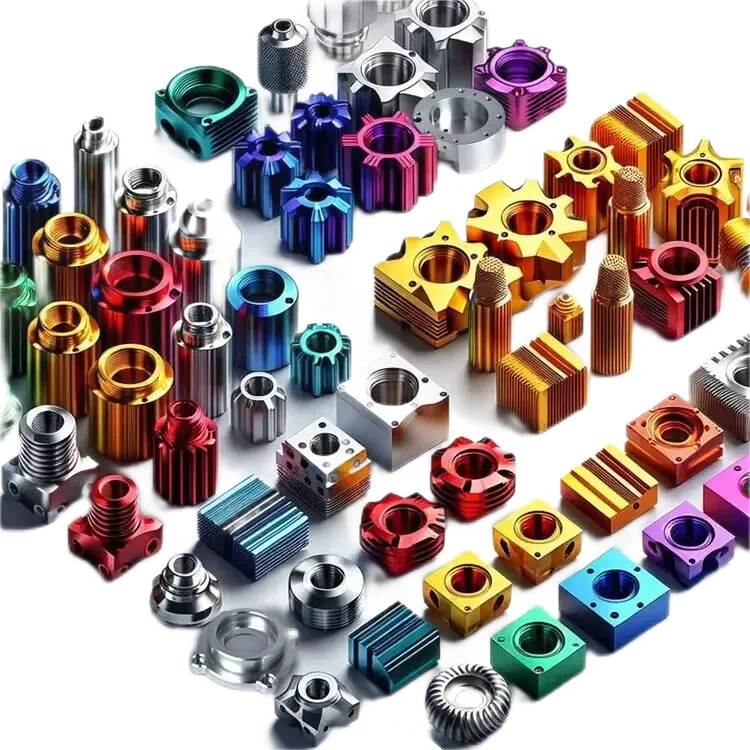
Specifying the correct surface finish is as critical as defining the geometric tolerances of a CNC machined component. For aluminum parts requiring a combination of superior aesthetics, enhanced wear resistance, and stringent environmental protection, the bead blast and anodize finish sequence remains the industry standard.
This guide provides engineering and procurement teams with a comprehensive technical analysis of combining bead blasting with Type II and Type III anodizing. We evaluate MIL-A-8625 standards, dimensional tolerance calculations, dielectric breakdown metrics, and real-world applications across high-performance sectors.
For projects requiring immediate technical evaluation, explore our custom aluminum anodizing services to consult directly with JLYPT surface finishing engineers.
1. The Mechanics of the Bead Blast + Anodize Sequence
The synergy between bead blasting and anodizing dictates the final part’s optical and mechanical properties. Bead blasting is a mechanical surface preparation method, while anodizing is an electrochemical conversion process.
1.1 Bead Blasting: Surface Topography Modification
Bead blasting utilizes pressurized air to propel spherical media (typically glass or ceramic) against the machined aluminum surface. Unlike sandblasting, which uses angular media (like aluminum oxide) to cut the material, bead blasting peens the surface.
Engineering Outcomes of Bead Blasting:
- Tool Mark Eradication: Eliminates CNC milling lines and feed marks, normalizing the surface topography to a uniform Ra (Roughness Average).
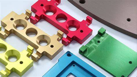
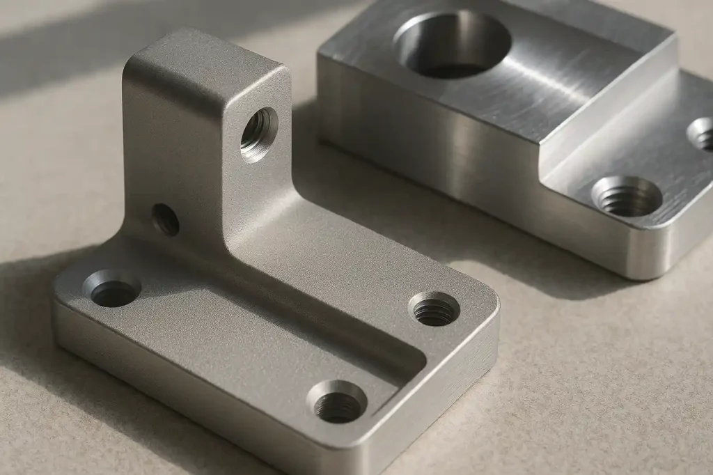
- Satin/Matte Finish Generation: Scatters reflected light, resulting in a non-directional matte appearance critical for optical and medical devices.
- Compressive Stress Induction: The peening effect introduces a thin layer of compressive residual stress, marginally improving fatigue life.
1.2 Anodizing: Electrochemical Oxide Growth
Following the bead blast, the part undergoes cleaning, etching, and desmutting before entering the electrolytic bath. Anodizing converts the aluminum surface into aluminum oxide (Al₂O₃). The matte texture created by the bead blast is permanently locked in and protected by the anodic layer.
2. MIL-A-8625 Standards: Type II vs. Type III Anodizing
Engineers must specify the correct anodizing type based on the application’s functional requirements. The benchmark standard is MIL-A-8625.
Type II: Sulfuric Acid Anodizing
Type II anodizing operates in a room-temperature sulfuric acid bath. It creates a porous oxide layer that accepts dyes exceptionally well.
- Primary Function: Corrosion resistance, decorative color matching, and moderate scratch resistance.
- Typical Thickness: 0.0001″ to 0.001″ (2.5 to 25 microns).
Type III: Hardcoat Anodizing
Type III, or hardcoat anodizing, utilizes a highly concentrated sulfuric acid bath maintained at near-freezing temperatures (approx. 32°F / 0°C) with higher current densities.
- Primary Function: Extreme wear resistance, high dielectric breakdown voltage, and superior corrosion protection.
- Typical Thickness: 0.0005″ to 0.0045″ (12.5 to 114 microns), standard being 0.002″ (50 microns).
Data Table 1: MIL-A-8625 Type II vs. Type III Technical Comparison
| Specification Metric | Type II (Standard Anodizing) | Type III (Hardcoat Anodizing) |
|---|---|---|
| Coating Thickness | 0.0001″ – 0.001″ (2.5 – 25 µm) | 0.0005″ – 0.0045″ (12.5 – 114 µm) |
| Dimensional Build-up | ~50% of coating thickness | ~50% of coating thickness |
| Microhardness (HV) | 200 – 300 HV | 400 – 600+ HV (Comparable to hardened steel) |
| Wear Resistance | Moderate (decorative) | High (Taber abrasion test < 1.5mg loss/1000 cycles) |
| Dielectric Breakdown | Low | High (Up to 800V per 0.001″ thickness) |
| Coloring/Dyeing | Excellent (Wide range of colors) | Limited (Dark grey, black, or natural dark bronze) |
| Porosity | High (Requires sealing) | Low (Often left unsealed for maximum wear resistance) |
3. Dimensional Tolerance Management
The most critical challenge in specifying a bead blast + anodize finish is calculating the final dimensional tolerances. Both processes alter the part’s geometry.
3.1 Material Removal via Bead Blasting
While bead blasting is primarily a peening process, aggressive blasting or the use of heavy ceramic media will remove trace amounts of material, typically reducing dimensions by 0.0001″ to 0.0003″. Threads and high-precision bores must be masked prior to blasting to prevent dimensional failure.
3.2 The 50/50 Rule of Anodic Growth
Unlike plating or painting, which strictly add material on top of the surface, anodizing converts the existing aluminum. The rule of thumb for both Type II and Type III is the 50/50 rule: 50% of the oxide layer penetrates the substrate, and 50% builds up outward.
Tolerance Calculation Example (Type III Hardcoat):
- Specified Coating Thickness: 0.002″ (50 µm)
- Penetration into Aluminum: 0.001″
- Build-up (Added dimension): 0.001″ per surface
- Total diameter increase on a solid cylinder: 0.002″
- Total diameter decrease on an internal bore: 0.002″
Data Table 2: Dimensional Change by Anodizing Thickness
| Target Coating Thickness | Penetration Depth | Surface Build-up | Impact on Solid Shaft Dia. | Impact on Internal Bore Dia. |
|---|---|---|---|---|
| 0.0005″ (Type II) | 0.00025″ | 0.00025″ | + 0.0005″ | – 0.0005″ |
| 0.0010″ (Type II/III) | 0.00050″ | 0.00050″ | + 0.0010″ | – 0.0010″ |
| 0.0020″ (Type III) | 0.00100″ | 0.00100″ | + 0.0020″ | – 0.0020″ |
Engineers must calculate pre-machining dimensions to account for this build-up, or utilize precision masking for critical tolerances. Partner with our engineering team via our custom aluminum anodizing services to ensure your CAD models reflect pre-plating requirements.
4. Industry Case Studies: Bead Blast + Anodize in Action
The theoretical benefits of this finish combination translate directly to performance metrics in demanding industries. Below are three verified applications demonstrating the functional necessity of this surface treatment.
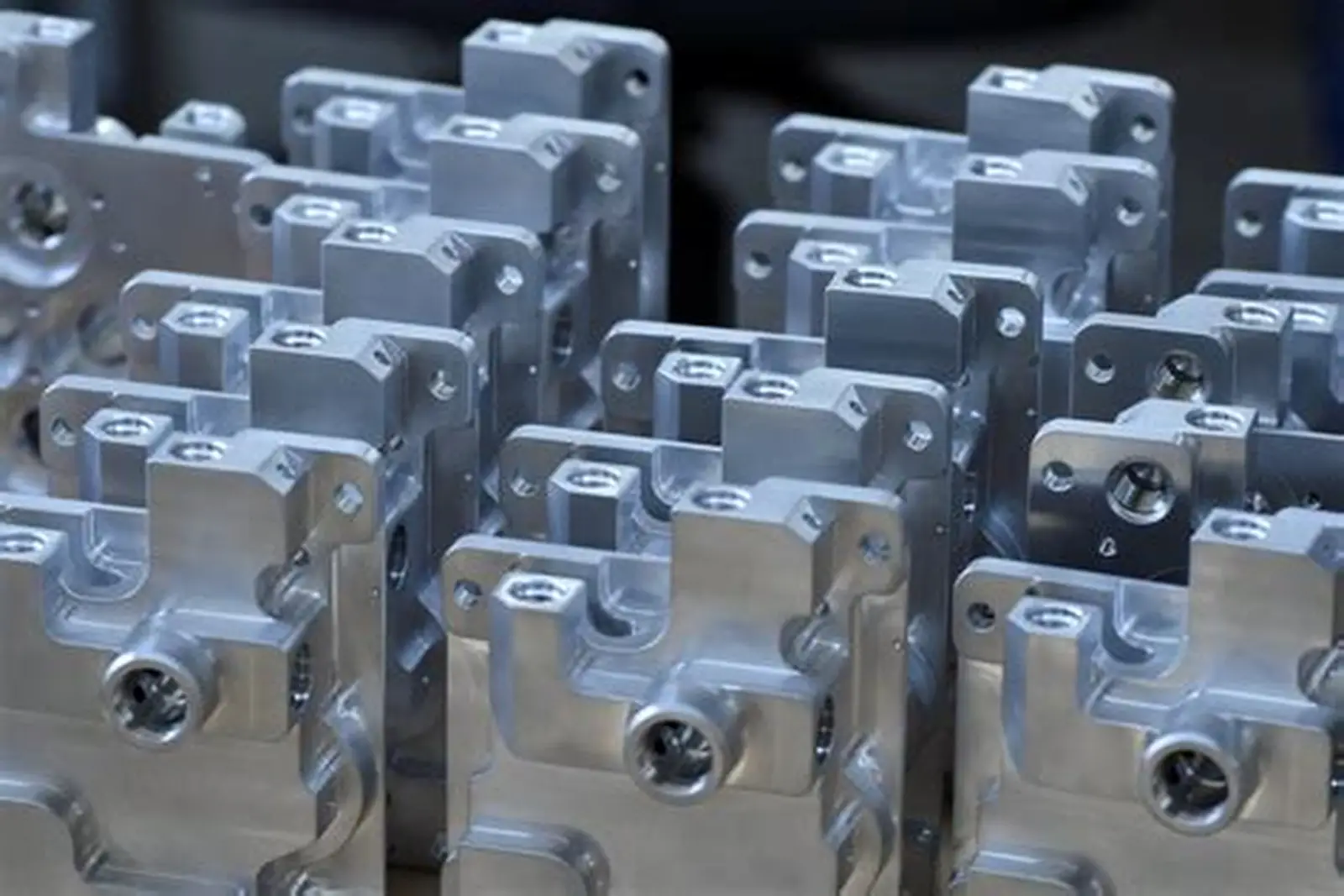
Case Study 1: Aerospace – Hydraulic Valve Housings
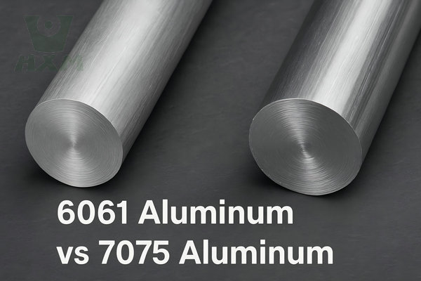
- Component: Aluminum 7075-T6 hydraulic fluid manifold.
- Requirement: Extreme wear resistance against internal fluid friction, elimination of external glare for maintenance visibility, and adherence to tight geometric tolerances.
- Solution: The exterior was subjected to a fine glass bead blast (Mil-Spec #8 media) to achieve a uniform matte finish. The entire part was then processed with MIL-A-8625 Type III, Class 2 (Black) hardcoat anodizing to a thickness of 0.002″. Critical internal threaded ports were masked using custom EPDM plugs.
- Result: The hardcoat provided a microhardness of 550 HV, preventing galling during high-pressure fluid cycles. The bead blast eliminated tooling marks that could have served as stress concentrators, enhancing the fatigue life of the manifold under cyclical loading.
Case Study 2: Medical – Surgical Robotic Arm Linkages
- Component: Aluminum 6061-T6 articulated joint linkages for an operating room robotic system.
- Requirement: Biocompatibility, strict anti-glare properties (to prevent blinding surgeons under high-intensity OR lights), and frequent sterilization resistance.
- Solution: A medium ceramic bead blast was applied to achieve a consistent Ra of 32 µin. This was followed by MIL-A-8625 Type II, Class 2 (Clear/Natural) anodizing with a hot DI water seal.
- Result: The bead blast + Type II clear anodize created a non-reflective, satin surface. The sealed anodic layer provided a chemically inert, biocompatible barrier that withstands repeated autoclave sterilization cycles without degrading or discoloring.
Case Study 3: Automotive – EV Battery Enclosure Mounts
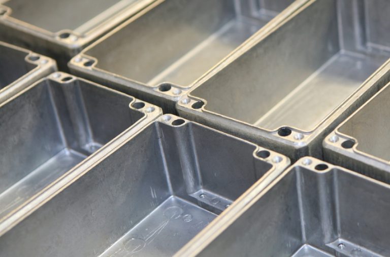
- Component: Aluminum 5052 mounting brackets for electric vehicle high-voltage battery modules.
- Requirement: Electrical insulation (high dielectric breakdown), galvanic corrosion resistance, and a uniform aesthetic for under-hood branding.
- Solution: The mounts received a coarse bead blast to hide raw material extrusion lines, followed by Type III hardcoat anodizing (unsealed).
- Result: The 0.002″ unsealed hardcoat anodized layer delivered a dielectric breakdown voltage exceeding 1200V DC, acting as a critical failsafe against electrical shorting between the battery module and the vehicle chassis. The bead blast ensured a premium, uniform grey appearance.
5. Design for Manufacturability (DFM) Guidelines
To maximize yield rates and minimize costs when specifying a bead blast and anodize finish, engineers must adhere to specific DFM principles during the CAD phase.
5.1 Edge Radii and Hardcoat Cracking
Unlike plating, anodic coatings grow perpendicular to the aluminum surface. On sharp 90-degree external corners, the oxide growth from the two adjacent surfaces intersects, creating a microscopic void or “corner defect.” This significantly reduces wear resistance and can cause the coating to chip.
- DFM Rule: Always specify minimum internal and external radii. For a 0.001″ coating, use a minimum radius of 0.032″. For a 0.002″ Type III coating, specify a minimum radius of 0.062″.
5.2 Blind Holes and Acid Entrapment
Anodizing requires submerging the part in liquid baths. Blind holes can trap sulfuric acid. If not thoroughly rinsed, the entrapped acid will bleed out post-anodizing, causing “white rust” and destroying the finish.
- DFM Rule: Avoid deep blind holes if possible. If required, specify a maximum depth-to-diameter ratio of 4:1. Ensure your manufacturing partner uses pressurized DI water rinsing or ultrasonic cleaning.
5.3 Masking Strategy
Bead blasting and anodizing require distinct masking strategies. Plugs used to block bead blasting media must endure mechanical impact, while anodizing masks must resist strong acids and electrical current.
- DFM Rule: Clearly define masking zones on the 2D engineering drawing. Indicate whether the zone is “No Bead Blast,” “No Anodize,” or both. Complex masking increases labor costs; design parts to minimize masking requirements where possible.
6. Quality Control and Defect Prevention
At JLYPT, ensuring the integrity of the bead blast and anodize finish involves rigorous quality assurance protocols.
- Coating Thickness Verification: Utilizing eddy current testing (ASTM B244) to verify the exact thickness of the anodic layer down to the micron, ensuring adherence to the 50/50 build-up calculation.
- Color Consistency: For Type II dyed parts, bead blasting provides a uniform canvas, but bath temperature and dye concentration must be strictly controlled. We use spectrophotometers to measure color within the Lab* color space, maintaining consistency across multiple production batches.
- Seal Quality Testing: For parts requiring maximum corrosion resistance (Type II), the anodic pores must be properly sealed. We conduct dye stain tests (ASTM B136) to confirm the integrity of the seal.
Conclusion
The combination of a bead blast and anodize finish offers an unparalleled balance of aesthetics, dimensional stability, and mechanical performance for CNC machined aluminum parts. By understanding the nuances of MIL-A-8625 standards, mastering the 50/50 dimensional build-up rule, and applying strict DFM principles, engineers can specify surface treatments that significantly elevate the lifespan and functionality of their components.
Whether your project involves aerospace fluid controls, medical robotics, or EV battery management systems, precise execution is non-negotiable.
Ready to optimize your component’s surface finish? Submit your CAD files and technical drawings to our engineering team today. Visit our custom aluminum anodizing services page for an in-depth DFM review and a rapid manufacturing quote.